Al technical title is built by PatSnap Al team. It summarizes the technical point description of the patent document.
a menstrual cup and cup body technology, applied in the field of menstrual cups, can solve the problems of difficult to remove, many users are allergic to the cup, and the cup generally lacks convenient and easy to grip portions, etc., and achieves the effect of flexible and resilien
Inactive Publication Date: 2008-03-27
DIVA INT INC
View PDF30 Cites 85 Cited by
Summary
Abstract
Description
Claims
Application Information
AI Technical Summary
This helps you quickly interpret patents by identifying the three key elements:
Problems solved by technology
Method used
Benefits of technology
[0005] In its broad aspect, the invention provides a menstrual cup for use in a vagina. The cup includes a receptacle extending from an open top end to a closed bottom end and a stem attached to the receptacle at the bottom end thereof, for use in removal of the cup. The receptacle includes a wall having an inner wall surface defining a cavity adapted for collecting fluid and an opposed outer wall surface. The open top end has a predetermined diameter, and the receptacle is adapted to be flexible and resilient. The wall comprises an upper rim portion at the top end of the receptacle for strengthening the top end, to maintain the cup in a preselected position in the vagina. Also, the wall comprises a transition portion extending-downwards from the rim portion towards the bottom end and a main portion extending from the transition portion to the bottom end of the receptacle portion. The transition portion is streamlined to define a profile which is substantially smooth.
Problems solved by technology
For instance, a typical cup includes a relatively sharply defined ridge positioned generally in the vicinity of an upper end thereof, which tends to interfere with the removal of the cup.
Although this relatively sharp ridge may assist in holding the cup in place, the ridge tends to interfere with removal of the cup, thereby sometimes causing discomfort.
In addition, the known cups generally lack convenient and easily gripped portions at the bottom ends thereof, to facilitate removal.
Alternatively, known cups may be made of natural latex rubber, however, this material has the disadvantage that many users are severely allergic to it.
Method used
Image
Click on the blue label to locate the original text in one second.
Reading with bidirectional positioning of images and text.
Examples
Embodiment Construction
)
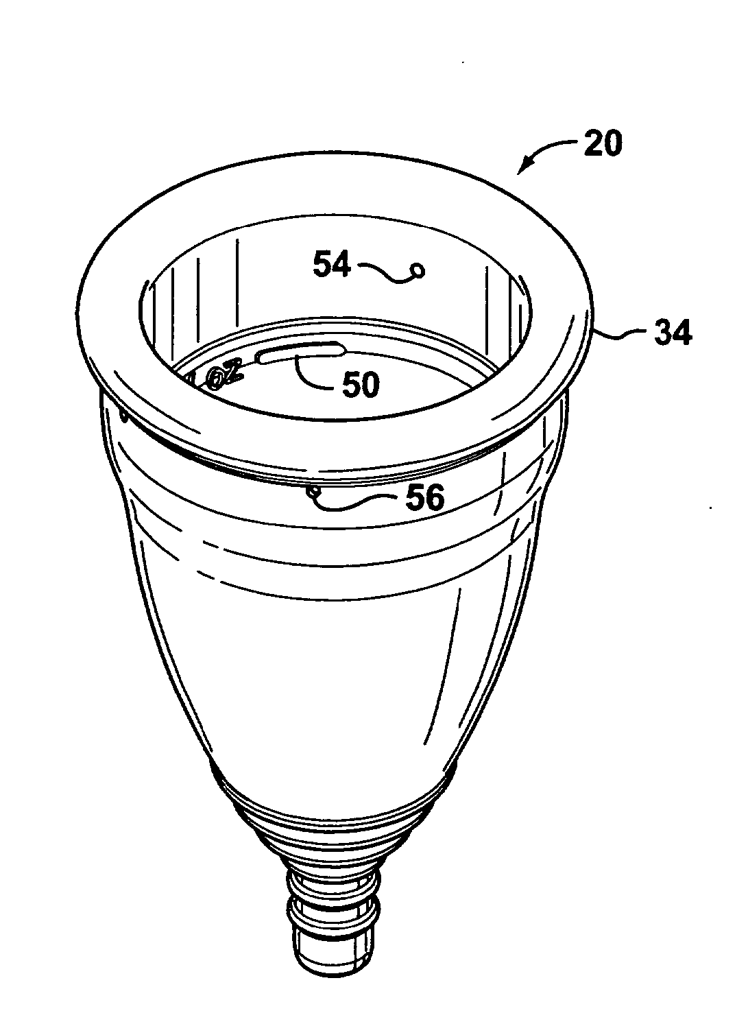
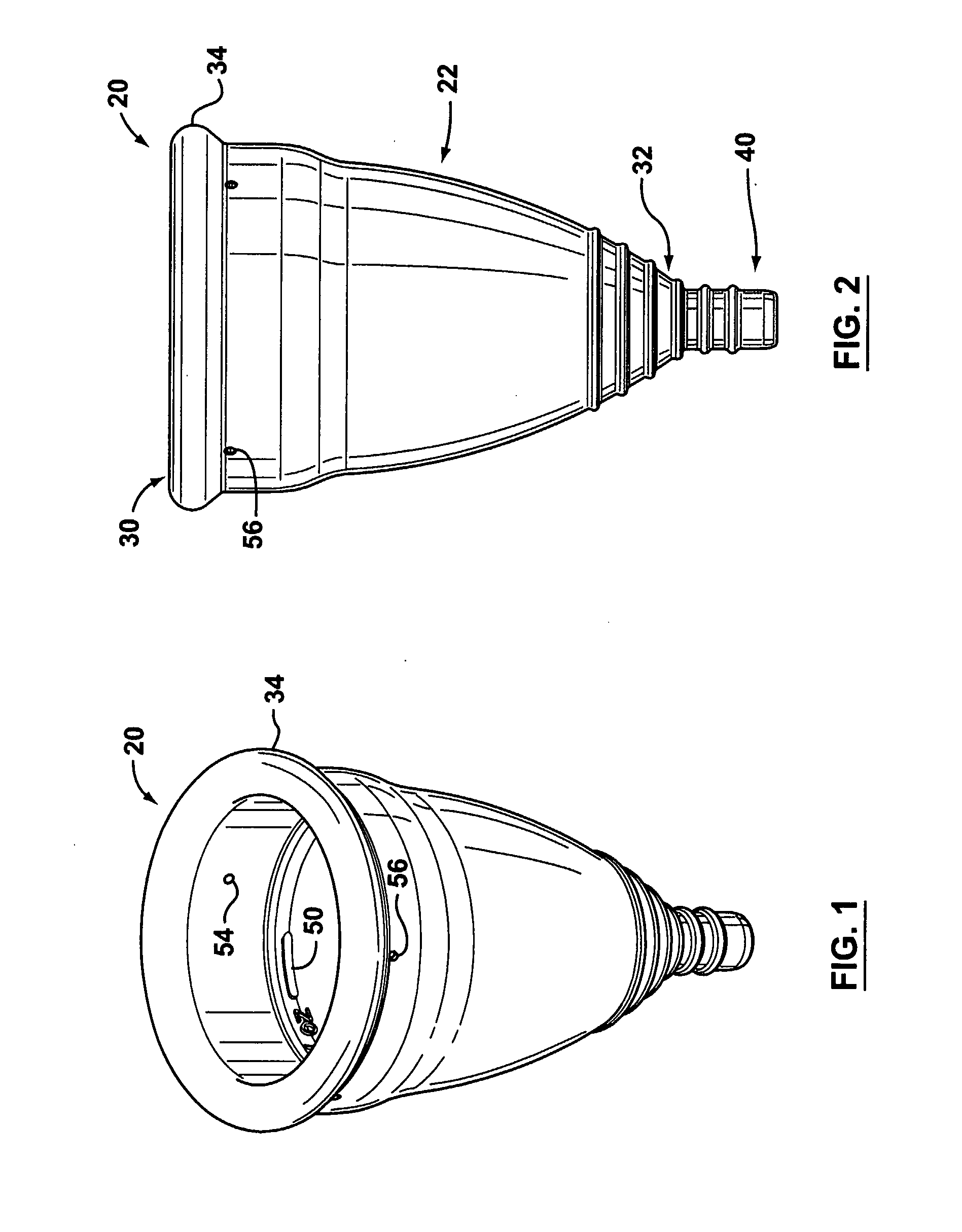
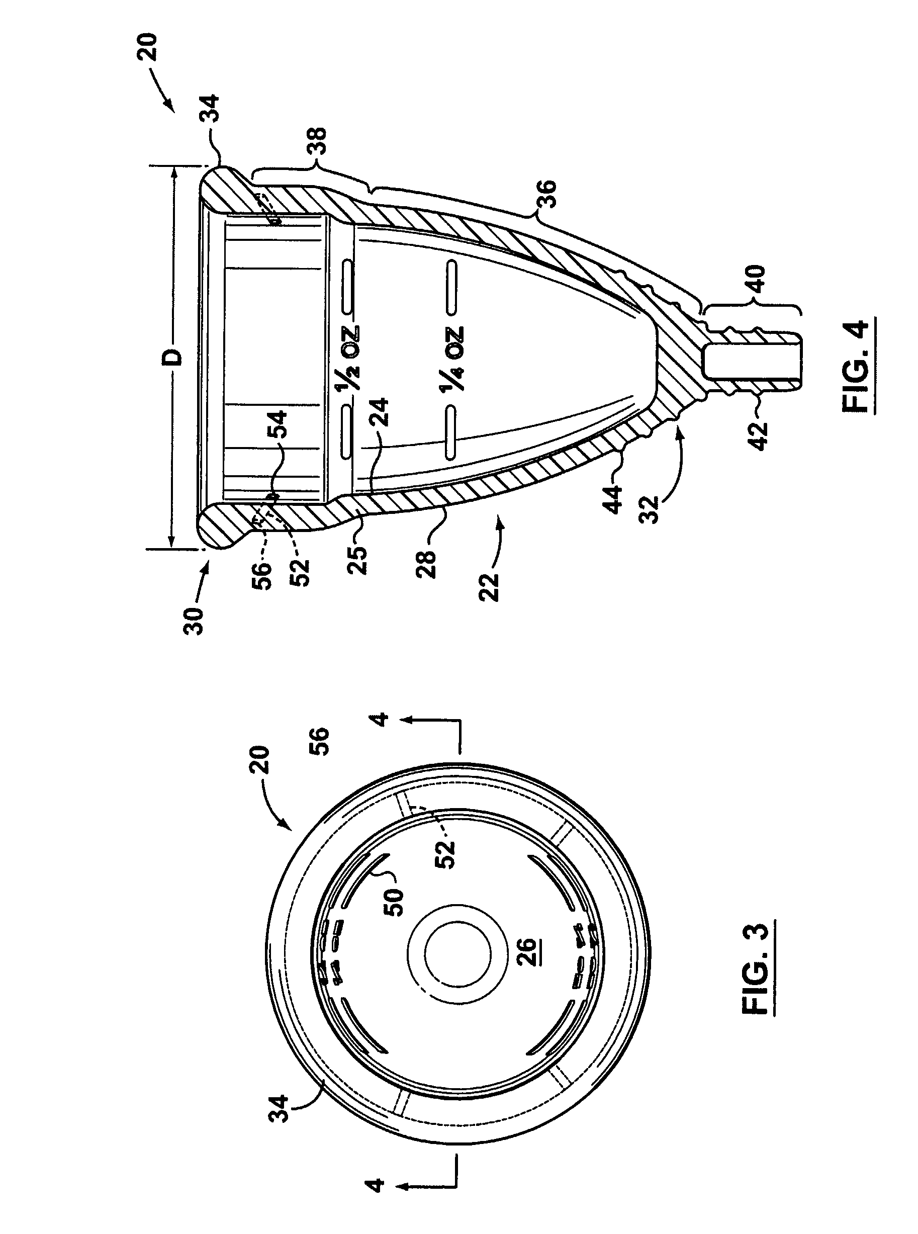
[0016] Reference is first made to FIG. 4 to describe a preferred embodiment of a cup in accordance with the invention indicated generally by the numeral 20. The cup 20, which is adapted for use in a vagina (not shown), includes a receptacle 22 having a wall 25 with an inner wall surface 24 which defines a cavity 26 adapted for collecting fluid (not shown), and an opposed outer wall surface 28. The receptacle 22 extends from an open top end 30 to a closed bottom end 32. The top end 30 preferably has a predetermined-outside diameter (shown as “D” in FIG. 4) and the receptacle 22 is adapted to be flexible and resilient, as will be described. The wall 25 includes an upper rim portion 34 which strengthens the top end 30, to maintain the cup 20 in a pre-selected position (not shown) in the vagina. Also, the wall 25 includes a main portion 36 thereof extending from the bottom end 32 towards the top end 30. The wall 25 additionally includes a transition portion 38 between the main portion ...
PUM
Abstract
A menstrual cup for use in a vagina. The cup includes a receptacle extending from an open top end to a closed bottom end and a stem attached to the receptacle at the bottom end thereof for use in removal of the cup. The receptacle comprises a wall having an inner wall surface defining a cavity adapted for collecting fluid and an opposed outer wall surface. The open top end has a predetermined diameter, the receptacle being adapted to be flexible and resilient. The outer wall surface includes an upper rim at the top end of the receptacle for strengthening the top end, a main portion extending from the bottom end of the receptacle portion towards the top end, and a transition portion between the main portion and the upper rim, the transition portion being streamlined to define a profile thereof which is substantially smooth.
Description
FIELD OF THE INVENTION [0001] This invention is related to menstrual cups. BACKGROUND OF THE INVENTION [0002] Menstrual cups are known, and various cups are disclosed in U.S. Pat. Nos. 1,891,761 (Goddard), 1,996,242 (Hagedom), 2,089,113 (Chalmers), Des. 323,212 (Crawford), and 5,827,248 (Crawford). [0003] However, known menstrual cups have a number of disadvantages. For instance, a typical cup includes a relatively sharply defined ridge positioned generally in the vicinity of an upper end thereof, which tends to interfere with the removal of the cup. Although this relatively sharp ridge may assist in holding the cup in place, the ridge tends to interfere with removal of the cup, thereby sometimes causing discomfort. Also, known cups can include a plurality of holes disposed proximal to the ridge, to equalize air pressure inside and outside the cup when it is inserted and when it is removed, thereby facilitating insertion and removal. In addition, the known cups generally lack conven...
Claims
Application Information
Patent Timeline
Application Date:The date an application was filed.
Publication Date:The date a patent or application was officially published.
First Publication Date:The earliest publication date of a patent with the same application number.
Issue Date:Publication date of the patent grant document.
PCT Entry Date:The Entry date of PCT National Phase.
Estimated Expiry Date:The statutory expiry date of a patent right according to the Patent Law, and it is the longest term of protection that the patent right can achieve without the termination of the patent right due to other reasons(Term extension factor has been taken into account ).
Invalid Date:Actual expiry date is based on effective date or publication date of legal transaction data of invalid patent.
Patent Type & Authority Applications(United States)