Device for controlling an air stream

a technology for controlling devices and air streams, applied in the direction of air-conditioning devices, transportation and packaging, vehicle heating/cooling devices, etc., can solve the problem that the torque required for sealing the air channel cannot be applied to the second sla

Active Publication Date: 2019-09-10
DR SCHNEIDER KUNSTWERKE
View PDF11 Cites 2 Cited by
  • Summary
  • Abstract
  • Description
  • Claims
  • Application Information

AI Technical Summary

Benefits of technology

[0007]It is therefore the object to indicate a device for controlling an air flow, which eliminates the disadvantages of the prior art and provides an economic, simple and reliable control of the air outflow direction and the amount of outflowing air.
[0018]The lever arrangement can comprise a second coupling element, which is rotatably coupled with the second bevel gear, with a first entrainer arranged eccentrically with respect to the axis of rotation of the second coupling element, and a lever element, which is rotatably arranged at the housing, with a first gate guide and a second gate guide, which are respectively arranged at a spacing from the axis of rotation of the lever element at opposite sections, wherein the first entrainer is mounted to be guidable in the first gate guide and the second entrainer is mounted to be guidable in the second gate guide, and wherein a second entrainer is arranged in the first end section of the first coupling element and rotatably connected with the first coupling rod. By virtue of the configuration of the lever arrangement, the rotation of the second bevel gear can be converted in simple mode and manner into a displacing movement of the first coupling rod and the second coupling rod. In addition, the first coupling rod and the second coupling rod can execute a compensating movement perpendicularly to the displacement direction.
[0023]The second slats can have a seal at least at the outer edges thereof extending parallel to the pivot axis and the housing can have in the region of the second slats a seal at least at inner side walls extending parallel to the pivot axis of the second slats. However, the seal at the second slats and in the housing can also be provided in encircling manner. The seal additionally improves sealing in a closed position of the second slats. The sealing means should preferably be selected so as to be flexible and resilient. In this way it is ensured that the sealing elements bear against the second slats and do not obstruct pivotation or swiveling thereof. For preference, plastics material foams or caoutchouc elements / caoutchouc foams or foams of rubber or foams of / with rubber components or elements or rubber can be used for that purpose.
[0027]Due to the fact that the important kinematic components—such as the first coupling rod, the lever element and / or the second coupling rod as well as the first coupling element—are arranged outside the housing, cross-sectional losses such as known from the prior art are avoided. In addition, in the case of the devices known from the prior art the important kinematic components are often visible, which detracts from the visual appearance of air vents of that kind. The just-described devices solve this problem, since the important components such as, for example, the lever arrangement are arranged outside the housing. Moreover, a further advantage in the case of the afore-described devices is that no cut-outs are needed in one of the slats, for example in the second slats. Thus, for example, DE 10 2013 100 534 A1 discloses the possibility of bringing the vertical slats into a closed position, but in the case of all embodiments at least one slat is provided with a large-area cut-out which unsatisfactorily fulfils air deflection and moreover produces additional turbulence in an air flow. Usually such cut-outs are required primarily for vertical slats in devices from the prior art, since the control element of these devices requires a point of engagement with the vertical slats.

Problems solved by technology

In the case of the devices known from the prior art, the rear vertical slats are always pulled, as a result of which the torque required for sealing closure of the air channel cannot be applied to the second slats.

Method used


Image

  • Device for controlling an air stream
  • Device for controlling an air stream
  • Device for controlling an air stream

Examples


Embodiment Construction

[0042]Parts which are provided in the figures with the same reference numerals substantially correspond with one another insofar as nothing to the contrary is indicated. Moreover, description of those components of the device 10 for controlling an air flow which are not essential to understanding of the technical teaching disclosed herein is dispensed with.

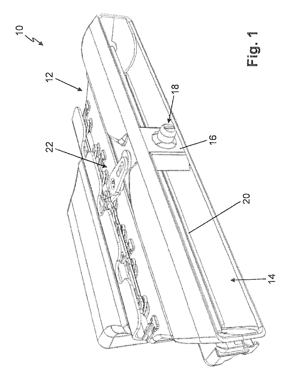
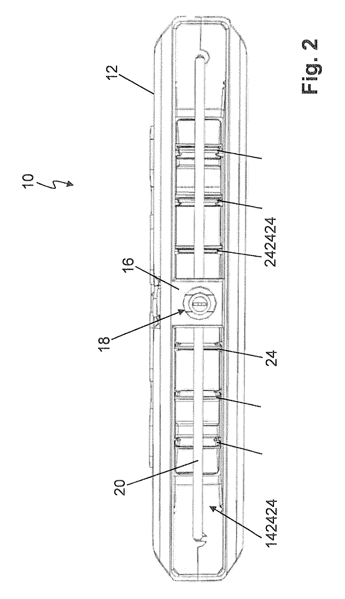
[0043]The devices 10 shown in the figures can be arranged, for example, in the region of a centre console of a vehicle dashboard. The devices 10 are in that case constructed as so-called broadband vents. This means that the devices 10 have a greater width than height in an air outlet region 14. The air outlet region 14 preferably has a width of more than 200 millimeters, preferably a width of more than 300 millimeters.

[0044]In the following description the terms “turning or rotating” and “pivotation or swiveling” are used synonymously. Thus, for example, pivotable slats are also rotatable about the pivot axes thereof and a rotatab...


PUM


Abstract

A device for controlling an air stream includes a control slat swivelly mounted in a housing and second slats extending orthogonally with respect to the control slat and swivelly mounted in the housing. The direction of the air stream exiting from the housing and the quantity of air streaming out can be set by the slats. An operating element is arranged orthogonally with respect to the longitudinal axis of the control slat to swivel and is coupled to a first bevel gear rotatably mounted on the bearing web and to the control slat. The first bevel gear is in engagement with a second bevel gear which is coupled to a lever arrangement which has at least one rotatably mounted first coupling member which is coupled to at least one first coupling rod and the at least one first coupling rod is coupled to the second slats.

Description

BACKGROUND OF THE INVENTION[0001]A device for controlling an air flow with at least one control slat pivotably mounted in a housing and with second slats extending orthogonally to the control slat and pivotably mounted in the housing is described, wherein the direction of the air flow exiting from the housing is settable by way of the control slat and the second slats and the amount of the exiting air is settable by way of the second slats.[0002]Various devices for controlling an air flow are known from the prior art, in which both the direction of the outflowing air and the amount of the outflowing air are settable by way of vertical slats arranged behind a control slat. Air direction and air quantity cannot be set independently of one another. The rear slats control the air direction and in the extreme setting close the air outlet.[0003]DE 10 2013 100 534 A1 discloses a device for controlling an air flow, wherein a front horizontal slat constructed as a control slat has a mount in...

Claims


Application Information

Patent Timeline
Patent Type & Authority Patents(United States)
IPC IPC(8): B60H1/34
CPCB60H1/3421B60H2001/3478B60H2001/3471B60H2001/3464B60H1/3428
Inventor GAREIS, JENNYSEEMANN, JÜRGENENDRES, GERHARD
Owner DR SCHNEIDER KUNSTWERKE
Why Eureka
Try Eureka