
Model predictive controller solution analysis process

a controller and model technology, applied in the field of control systems, can solve problems such as inability to know how much to change a constraint, require offline simulation, and take a significant amount of time to understand

Active Publication Date: 2008-03-27
EXXON RES & ENG CO
View PDF99 Cites 25 Cited by
  • Summary
  • Abstract
  • Description
  • Claims
  • Application Information

AI Technical Summary

Benefits of technology

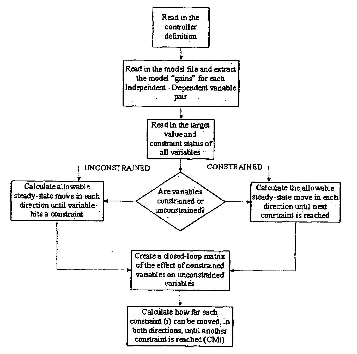
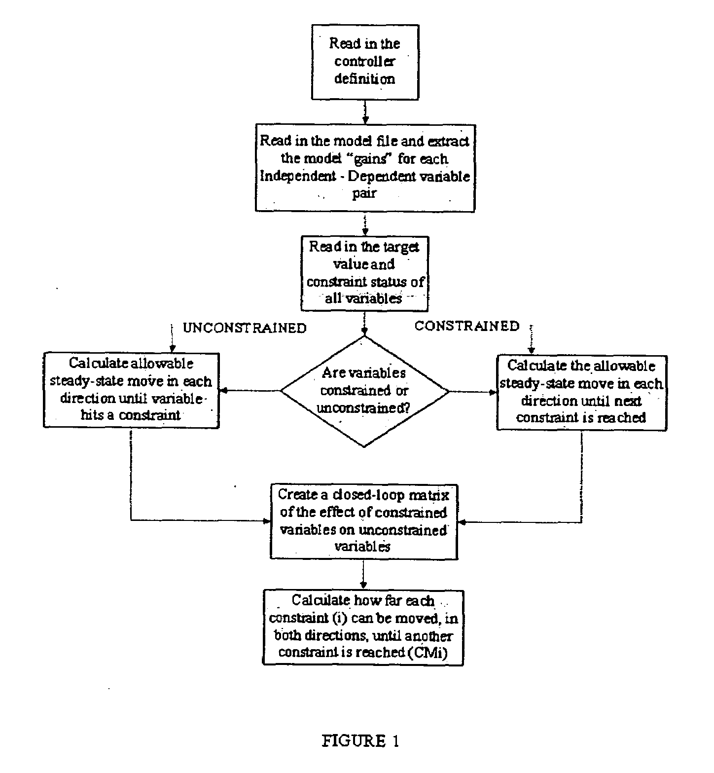
[0009]Aspects of embodiments of the invention relate to a method to analyze and describe a solution from an MPC that can provide quantitative input to an operator regarding the effect of changing controller limits in an MPC solution.

Problems solved by technology

However, larger, more interactive problems, often require offline simulation.
This can take a significant amount of time to understand, even qualitatively.
Otherwise, the operator cannot know how much to change a constraint or which constraint is the next to become active.
However, this approach does not provide quantitative answers as to how much any operator change will affect the controller solution.

Method used


Image

  • Model predictive controller solution analysis process
  • Model predictive controller solution analysis process
  • Model predictive controller solution analysis process

Examples


Embodiment Construction

[0017]A preferred embodiment of this invention described herein is directed to a dynamic matrix controller (DMC). However, the invention is intended to apply more broadly to multivariable predictive controllers (MPC) in general and to control schemes in which it is desirable to optimize process limits in various applications.

[0018]The term operator used herein is intended to refer to any end user. For example, an end user could be an operator, a process engineer, a shift lead, a control engineer, or a manager.

[0019]To demonstrate the basic functionality of the invention, a simple problem is addressed. In the simplest form, a constraint sensitivity analysis tool for a DMC controller is provided with no transforms, no ramps, and no minimum move MVs. The basic functions include a constrained variable analysis, which determines how much a constraint can be moved before the next constraint becomes active, and identifies the next constraint. An unconstrained variable analysis is also acco...


PUM


Abstract

The solution from a multivariable predictive controller (MPC) is analyzed and described by providing quantitative input to operators regarding the effect of changing controller limits on the MPC controller solution. This information allows a rapid operator response to changes and more optimal process operation.

Description

BACKGROUND OF THE INVENTION[0001]1. Field of the Invention[0002]This invention relates to control systems and, more particularly, to methods of driving dynamic and steady-state behavior of a process toward more optimum operating conditions.[0003]2. Discussion of Related Art[0004]Multivariable predictive control algorithms, such as DMCplus™ from AspenTech® of Aspen Technologies, Inc. or RMPCT from Honeywell International Inc., are a combination of calculations to drive the dynamic and steady-state behavior of a process toward a more optimum operating condition. The steady-state algorithm used in the control scheme is most commonly a linear program (LP), but sometimes is a quadratic program (QP). For small problems, understanding the LP or QP solution is relatively simple. Two-dimensional problems can be visualized on a paper and demonstrated to an operator to gain understanding of the process. With some detailed modeling background, engineers and well trained operators can understand...

Claims


Application Information

Patent Timeline
Patent Type & Authority Applications(United States)
IPC IPC(8): G05B13/02
CPCG05B13/048
Inventor PETERSON, TOD J.PUNURU, ADI R.EMIGHOLZ, KENNETH F.WANG, ROBERT K.BARRETT-PAYTON, DAVE
Owner EXXON RES & ENG CO
Learn More