Electrolytic copper plating solution analyzer, and electrolytic copper plating solution analysis method

a technology of electrolytic copper plating solution and analyzer, which is applied in the direction of electrolysis components, instruments, material electrochemical variables, etc., can solve the problems of complex operations and additives that undergo decomposition, and achieve accurate quantitative control

Active Publication Date: 2016-12-29
TOPPAN PRINTING CO LTD
View PDF0 Cites 3 Cited by
  • Summary
  • Abstract
  • Description
  • Claims
  • Application Information

AI Technical Summary

Benefits of technology

[0065]According to the above embodiments of the invention, when the potential between the working electrode and the reference electrode, both immersed in analysis sample of an electrolytic copper plating solution, is measured to analyze the relation between an elapsed time and the potential, parameters indicating a condition of the electrolytic copper plating solution are calculated based on such a reaction mechanism that a Cu(I) species or an inhibitor is replaced with a leveler as the deposition reaction of a copper plated film proceeds, and the Cu(I) species forms a complex at least with a promoter to show a promotion function. Therefore, when the condition of the electrolytic copper plating solution containing additives is controlled by use of a constant current electrolytic technique, more accurate quantitative control becomes possible.
[0066]It should be noted that on this occasion, the inhibitor is substituted with the Cu(I) species, or the inhibitor is substituted with the Cu(I), which is then further substituted with the leveler, or the inhibitor is substituted with the Cu(I) species and the inhibitor is further substituted with leveler.

Problems solved by technology

However, as time passes from a plating reaction initiation point, the additives undergo decomposition or property changes, and the control therefor is necessary.
However, although the analysis methods disclosed in PTLs 1 and 2 are feasible by the use of existing CVS devices, complicated operations are needed.

Method used


Image

  • Electrolytic copper plating solution analyzer, and electrolytic copper plating solution analysis method
  • Electrolytic copper plating solution analyzer, and electrolytic copper plating solution analysis method
  • Electrolytic copper plating solution analyzer, and electrolytic copper plating solution analysis method

Examples


first embodiment

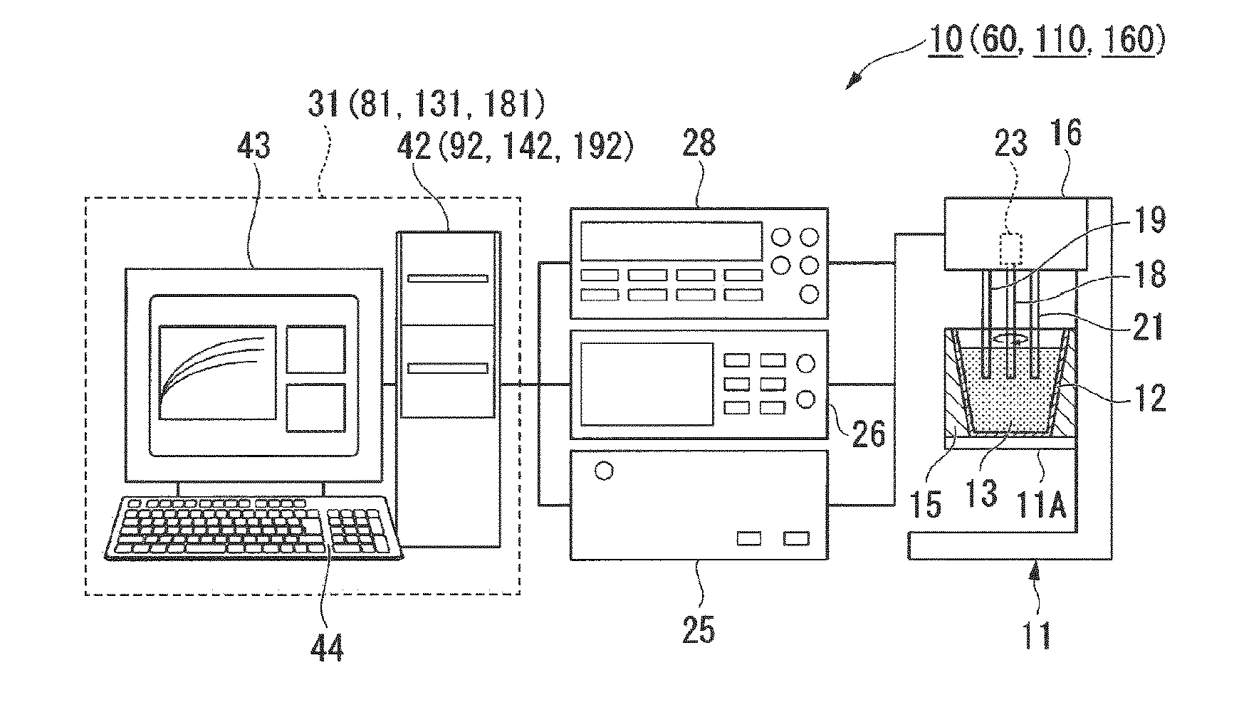
[0075]An electrolytic copper plating solution analyzer according to a first embodiment of the invention is now described.

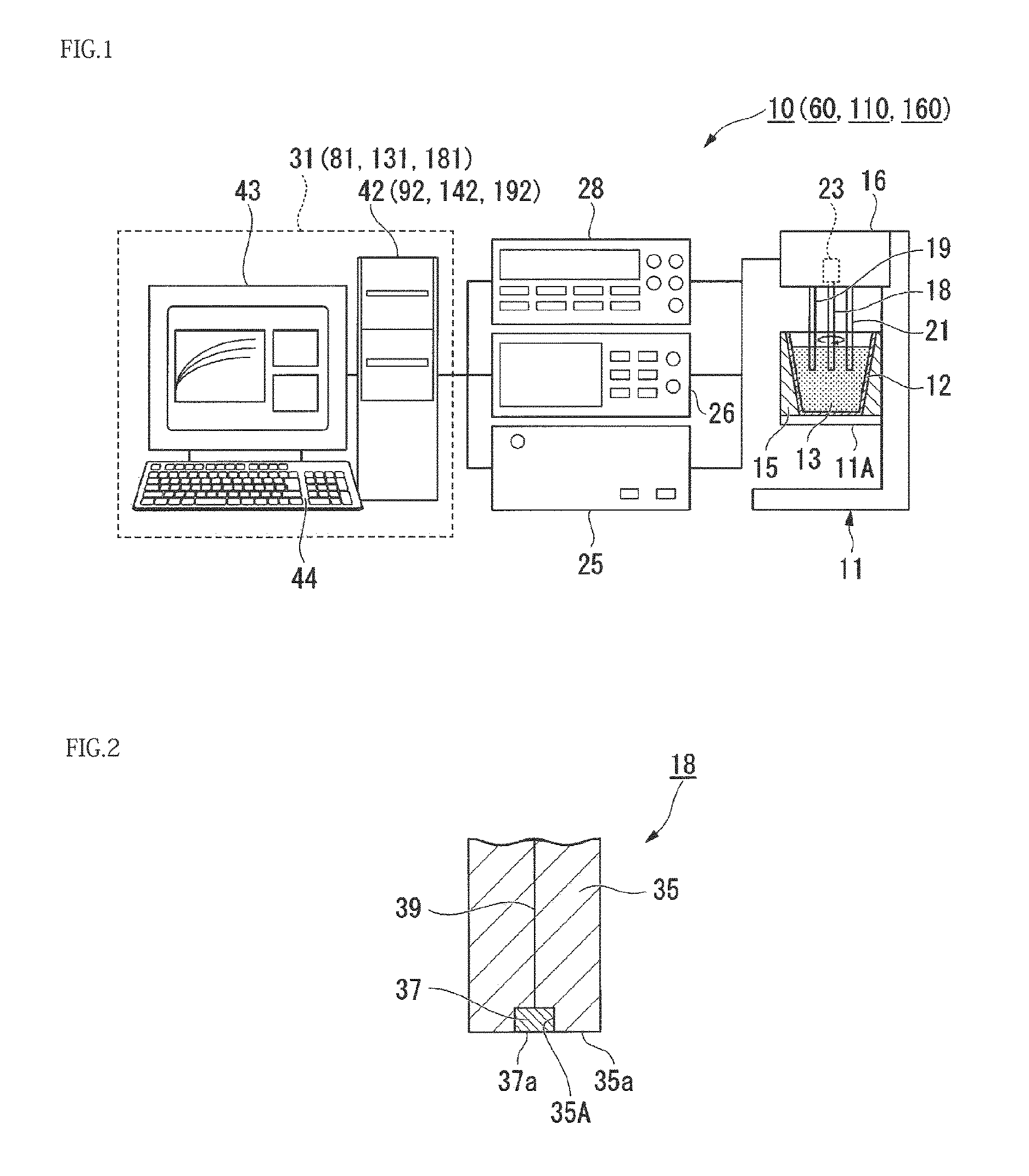
[0076]FIG. 1 is a schematic view showing an example of a configuration of an electrolytic copper plating solution analyzer of the first embodiment of the invention. FIG. 2 is a view showing an example of a tip portion of a working electrode used in the electrolytic copper plating solution analyzer of the first embodiment of the invention.

[0077]As shown in FIG. 1, an electrolytic copper plating solution analyzer 10 of the present embodiment includes a stand 11, an analysis container 12, a temperature holding unit 15, an electrode support 16, a working electrode 18, a reference electrode 19, a counter electrode 21, a rotation drive unit 23, a current generation unit 26, a potential measurement unit 28, a controller 25 and an analysis unit 31.

[0078]The stand 11 has a stage portion 11A mounting the analysis container 12 and the temperature holding unit 15 thereon.

[007...

second embodiment

[0246]An electrolytic copper plating solution analyzer of a second embodiment of the present invention is illustrated.

[0247]As shown in FIG. 1, an electrolytic copper plating solution analyzer 60 of the present embodiment is provided with an analysis unit 81 in place of the analysis unit 31 of the electrolytic copper plating solution analyzer 10 of the first embodiment.

[0248]The analysis unit 81 is provided with an analysis unit body 92 in place of the analysis unit body 42 of the analysis unit 31.

[0249]The description below is centered around a difference from the first embodiment.

[0250]The analysis unit body 92 differs from the first embodiment in that the measurement data of potential η are analyzed by using the following equations (5) to (8) instead of the foregoing equations (1) to (4).

[0251]It will be noted that the equations (6), (7) and (8) are similar to the equations (2), (3) and (4) in the first embodiment. Among the constants and variables used in the respective equation...

third embodiment

[0305]An electrolytic copper plating solution analyzer according to a third embodiment of the invention is described.

[0306]As shown in FIG. 1, an electrolytic copper plating solution analyzer 110 of the present embodiment has an analysis unit 131 in place of the analysis unit 31 of the electrolytic copper plating solution analyzer 10 of the first embodiment.

[0307]The analysis unit 131 has an analysis unit body 142 instead of the analysis unit 42 of the analysis unit 31.

[0308]The description below is centered around a difference from the first embodiment.

[0309]A difference from the first embodiment resides in that the analysis unit body 142 makes use of the following equations (41) and (61) to (63) instead of the foregoing equations (1) to (4) so as to analyze the measured data of potential η.

[0310]It will be noted that the equations (61), (62) and (63) are the same as the equations (2), (3) and (4) in the first embodiment, respectively. Of the constants and variables used in the res...


PUM

PropertyMeasurementUnit
temperatureaaaaaaaaaa
surface areaaaaaaaaaaa

Abstract

An electrolytic copper plating solution analyzer comprises an analysis container for accommodating a part of an electrolytic copper plating solution containing additives including a promoter, an inhibitor and a leveler, a working electrode immersed in the electrolytic copper plating solution accommodated in the analysis container, a reference electrode immersed in the electrolytic copper plating solution and used as a reference when a potential of the working electrode is determined, a counter electrode immersed in the electrolytic copper plating solution, a rotation drive unit for rotating the working electrode at a given speed, a current generation unit passing an electric current with a given current density between the working electrode and the counter electrode, a potential measurement unit for measuring the potential between the working electrode and the reference electrode, and an analysis unit for analyzing the relationship between an elapsed time after the current passage and the potential.

Description

CROSS-REFERENCE TO RELATED PATENT APPLICATIONS[0001]This application is a continuation application filed under 35 U.S.C. §111(a) claiming the benefit under 35 U.S.C. §§120 and 365(c) of International Application No. PCT / JP2015 / 057164 filed on Mar. 11, 2015, which is based upon and claims the benefit of priority of Japanese Patent Application No. 2014-048161, filed on Mar. 11, 2014, and Japanese Patent Application No. 2014-251155, filed on Dec. 11, 2014 the entire contents of which are all hereby incorporated by reference.TECHNICAL FIELD[0002]This invention relates to an electrolytic copper plating solution analyzer and also to a method for analyzing an electrolytic copper plating solution. More particularly, the invention relates to an electrolytic copper plating solution analyzer wherein an electrolytic copper plating solution is analyzed, which is used to deposit and grow an electrolytic copper plated film in a via hole (contact hole) or a through hole formed in high-density mount...

Claims


Application Information

Patent Timeline
Patent Type & Authority Applications(United States)
IPC IPC(8): G01N27/42
CPCG01N27/423G01N27/4161C25D3/12C25D3/22C25D3/38C25D3/58C25D21/12G01N27/42
Inventor KOSUGI, MASAHIROOKUBO, TOSHIKAZU
Owner TOPPAN PRINTING CO LTD
Why Eureka
Try Eureka