Driving Device for Display Panel, Display Device Including the Driving Device, Method for Driving a Display Panel, Program, and Storage Medium

Active Publication Date: 2008-04-03
SHARP KK
View PDF15 Cites 48 Cited by
  • Summary
  • Abstract
  • Description
  • Claims
  • Application Information

AI Technical Summary

Benefits of technology

[0019] As a result of this, it is possible to display the color signals of the interpolated sub-pixels for a color of each of the color filters corresponding to the sub-pixels.
[0020] Thus, it is possible to provide (i) a driving device for a display panel which is capable

Problems solved by technology

Meanwhile, there is the fact that a human is sensitive to luminance and able to recognize even a slight variation of luminance, but is not able to recognize slight variation of hue.
However, (i) a driving device for a liquid crystal display panel including color filters arranged in the conventional matrix pattern of 2-by-2 sub-pixels and (ii) a liquid crystal display device including the driving device have the following problem.
That is, it is difficult to respond to, for example, scale change of a screen or other event because incoming signals are in one-to-one correspondence with display

Method used


Image

  • Driving Device for Display Panel, Display Device Including the Driving Device, Method for Driving a Display Panel, Program, and Storage Medium
  • Driving Device for Display Panel, Display Device Including the Driving Device, Method for Driving a Display Panel, Program, and Storage Medium
  • Driving Device for Display Panel, Display Device Including the Driving Device, Method for Driving a Display Panel, Program, and Storage Medium

Examples


Embodiment Construction

[0062] The following description will discuss one embodiment of the present invention with reference to FIGS. 1 through 16.

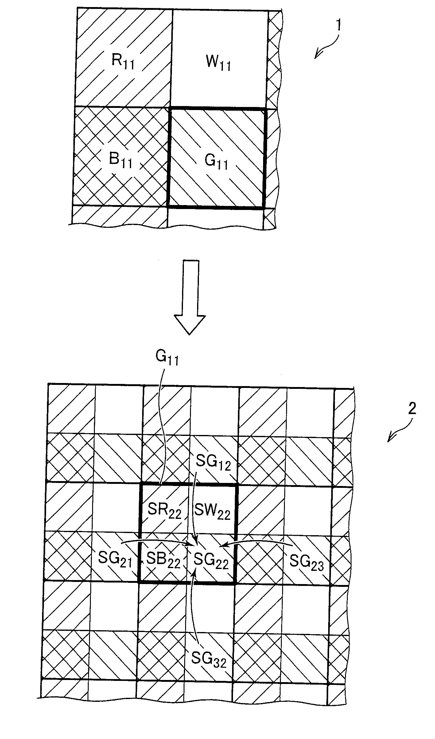
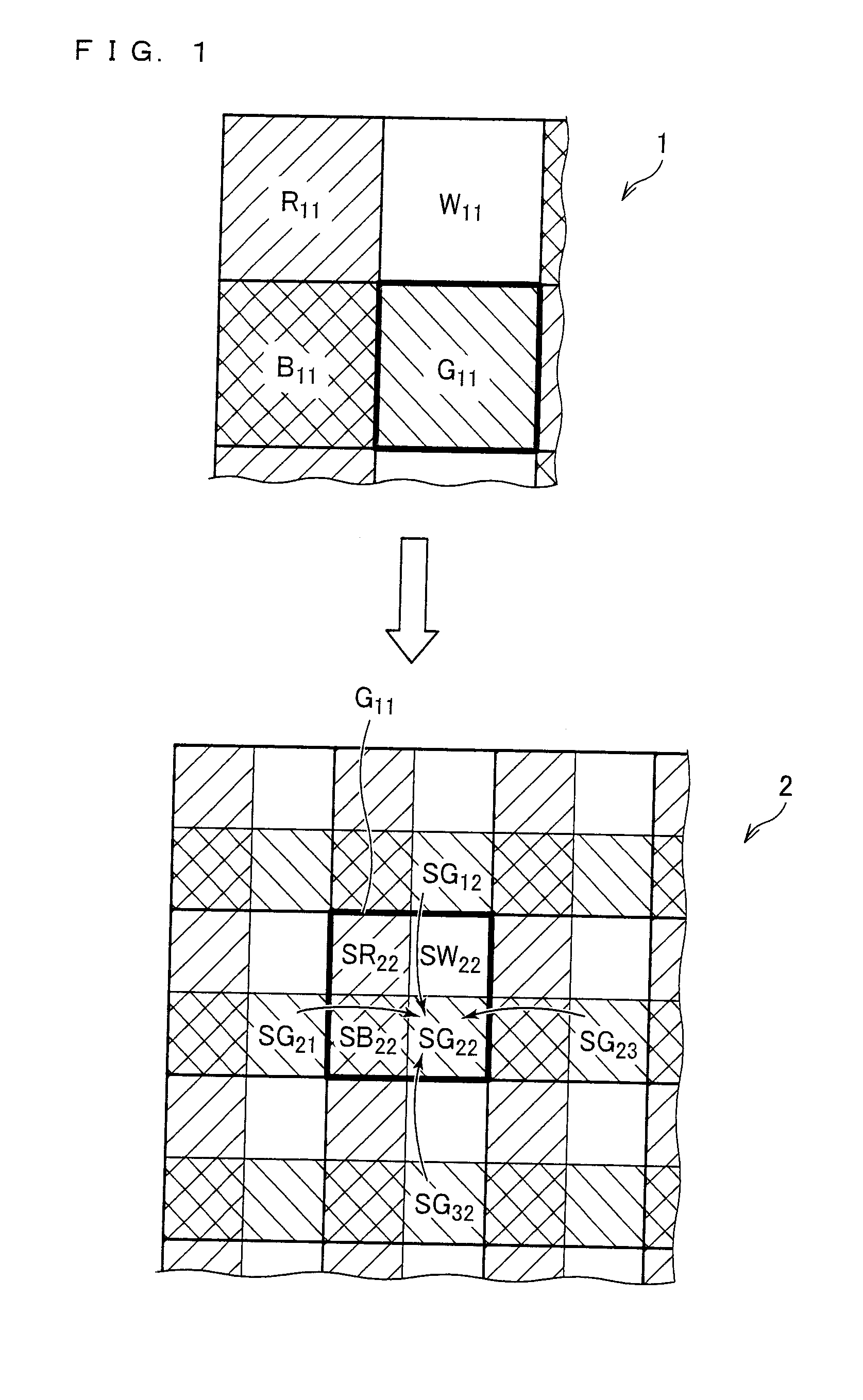
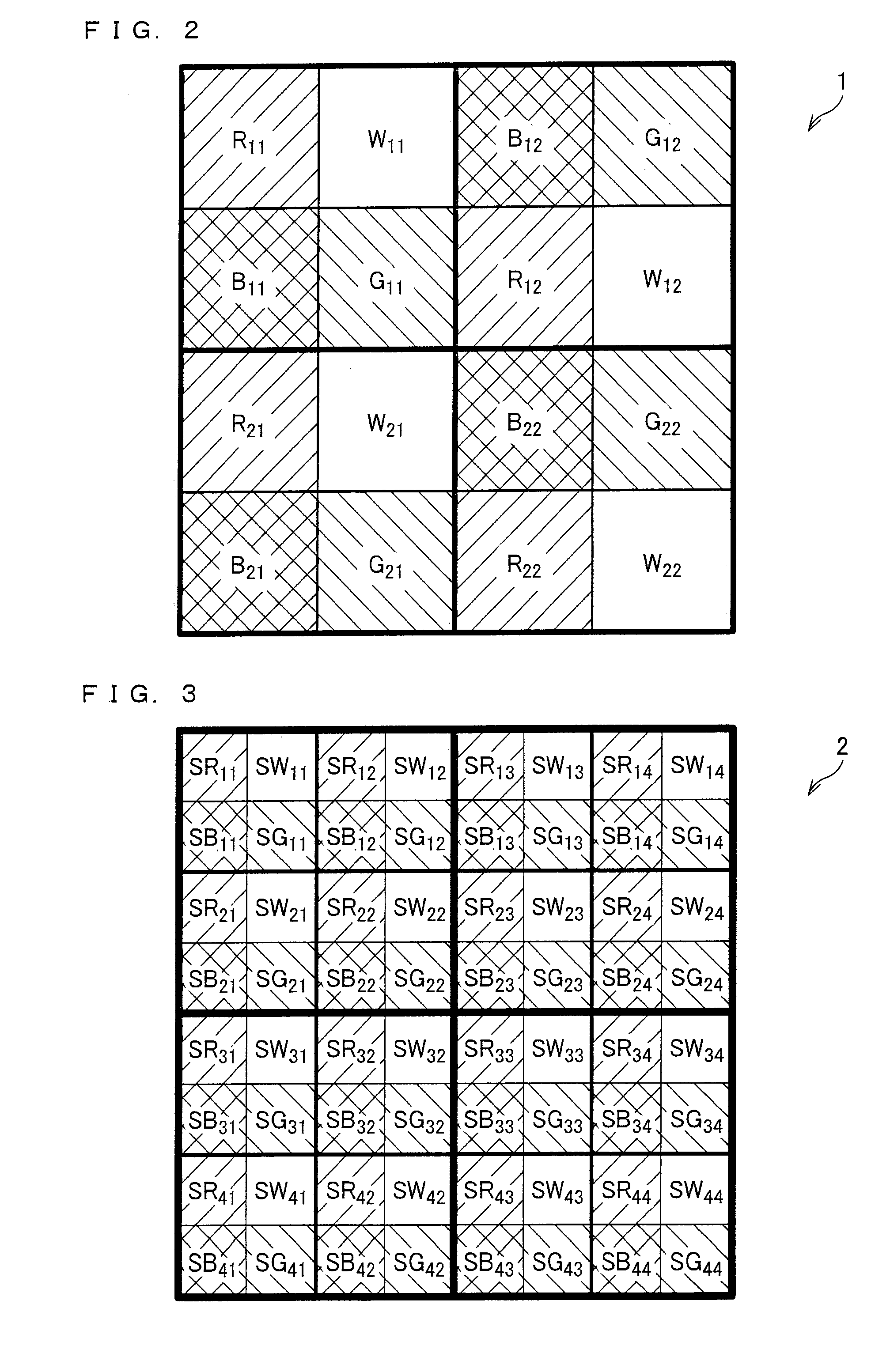
[0063] In a driving device for a display panel according to the present embodiment and a display device including the driving device, a color filter is made for four pixels, each of which is composed of four sub-pixels of red (R), green (G), blue (B), and white (W), being arranged in a matrix pattern of 2-by-2 pixels per block, as illustrated in FIG. 2.

[0064] More specifically, in a color filter 1 of the present embodiment, pixel (1, 1) and pixel (2, 1) each has red (R), blue (B), green (G), and white (W) in this order counterclockwise, whereas pixel (1,2) and pixel (2,2) each has blue (B), red (R), white (W), and green (G) in this order counterclockwise. Such combinations of four pixels per block realize a pattern of the color filter 1 that places importance on luminance balance.

[0065] Incidentally, in the present embodiment, in displaying an incoming signal...


PUM


Abstract

A display panel is the one in which a pixel composed of sub-pixels of red (R), green (G), blue (B), and at least one other color has two sub-pixels at least in a vertical scanning direction, and color filters are provided respectively corresponding to the sub-pixels. There are provided: an incoming signal interpolating section which interpolate each of pixels based on incoming color signal components of red (R), green (G), and blue (B) at least in a vertical scanning direction to generate interpolated RGB signals; a luminance signal converting section which converts color signals of interpolated sub-pixels, which are obtained from the incoming signal interpolating section, into luminance signals; an another color luminance component adding section which adds a luminance signal component of at least one other color on a basis of luminance signal components of colors of red (R), green (G), and blue (B), which components are outputted from the luminance signal converting section; and a luminance reallocating section which reallocates luminance signals of peripheral interpolated sub-pixels, for a color of each of the color filters corresponding to the sub-pixels, in accordance with output from the another color luminance component adding section.

Description

TECHNICAL FIELD [0001] The present invention relates to (i) a driving device for a display panel in which a pixel composed of sub-pixels of red (R), green (G), blue (B), and at least one other color has a plurality of sub-pixels at least in a vertical scanning direction, and color filters are provided corresponding to the respective sub-pixels, and (ii) a display device including the driving device. BACKGROUND ART [0002] As disclosed in Japanese Unexamined Patent Publication No. 118521 / 1990 (Tokukaihei 2-118521; published on May 2, 1990), for example, the conventional liquid crystal display devices have blocks of color filters arranged in a pattern of locations for the increase of luminance. Each of the blocks is composed, as a unit block, of a color filter of white (W) as well as color filters of red (R), green (G), and blue (B). More specifically, in the liquid crystal display devices, white light is emitted from a backlight such as a fluorescent lamp, for example, passes through ...

Claims


Application Information

Patent Timeline
IPC IPC(8): G09G5/10
CPCG09G3/2003G09G2340/06G09G2340/0457
Inventor SHIOMI, MAKOTO
Owner SHARP KK
Why Eureka
Try Eureka