Fuel cell startup method for fast freeze startup

a fuel cell and startup method technology, applied in the direction of battery/fuel cell propulsion, battery/cell control arrangement, electrochemical generators, etc., can solve the problems of changing the operating requirements of the startup method, components of the fuel cell system to freeze, etc., to increase the temperature ramp-up rate of the fuel cell system, optimize the warm-up time, and increase the fuel cell system's temperature ramp-up rate

Active Publication Date: 2008-04-03
GM GLOBAL TECH OPERATIONS LLC
View PDF11 Cites 29 Cited by
  • Summary
  • Abstract
  • Description
  • Claims
  • Application Information

AI Technical Summary

Benefits of technology

The present invention provides an improved method for starting a cold or frozen fuel cell while balancing its heating process. By rapidly loading the fuel cell stack and considering various usage scenarios, this method prevents damage from excessive temperatures or insufficient power output. Additionally, this approach reduces the amount of time needed for the fuel cell system to reach optimal operating conditions after being turned off.

Problems solved by technology

The technical problem addressed in this patent text needs to be identified by a senior R&D personnel who has read it through.

Method used


Image

  • Fuel cell startup method for fast freeze startup
  • Fuel cell startup method for fast freeze startup
  • Fuel cell startup method for fast freeze startup

Examples


Embodiment Construction

[0012]The following detailed description and appended drawings describe and illustrate various exemplary embodiments of the invention. The description and drawings serve to enable one skilled in the art to make and use the invention, and are not intended to limit the scope of the invention in any manner. In respect of the methods disclosed, the steps presented are exemplary in nature, and thus, the order of the steps is not necessary or critical.

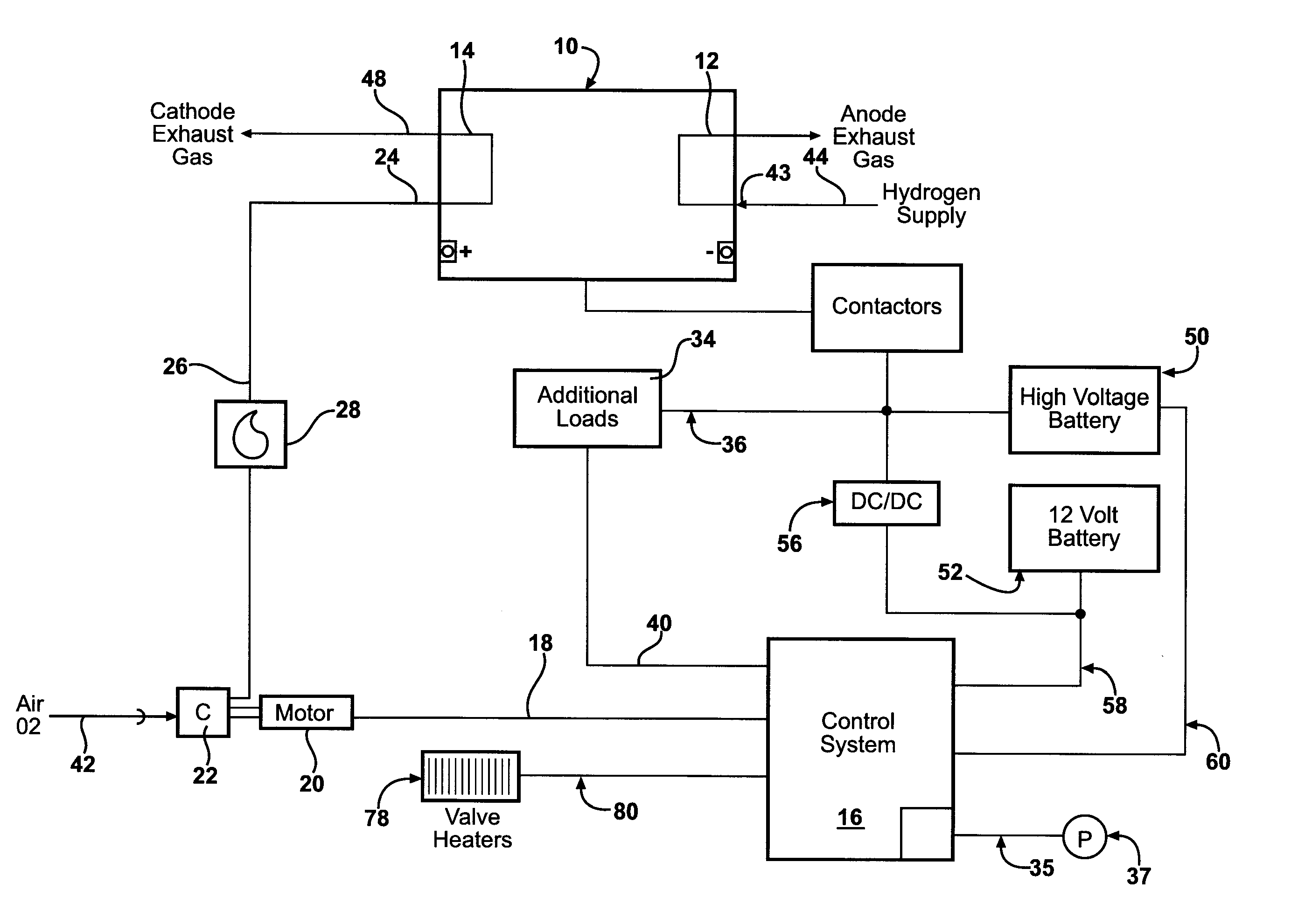
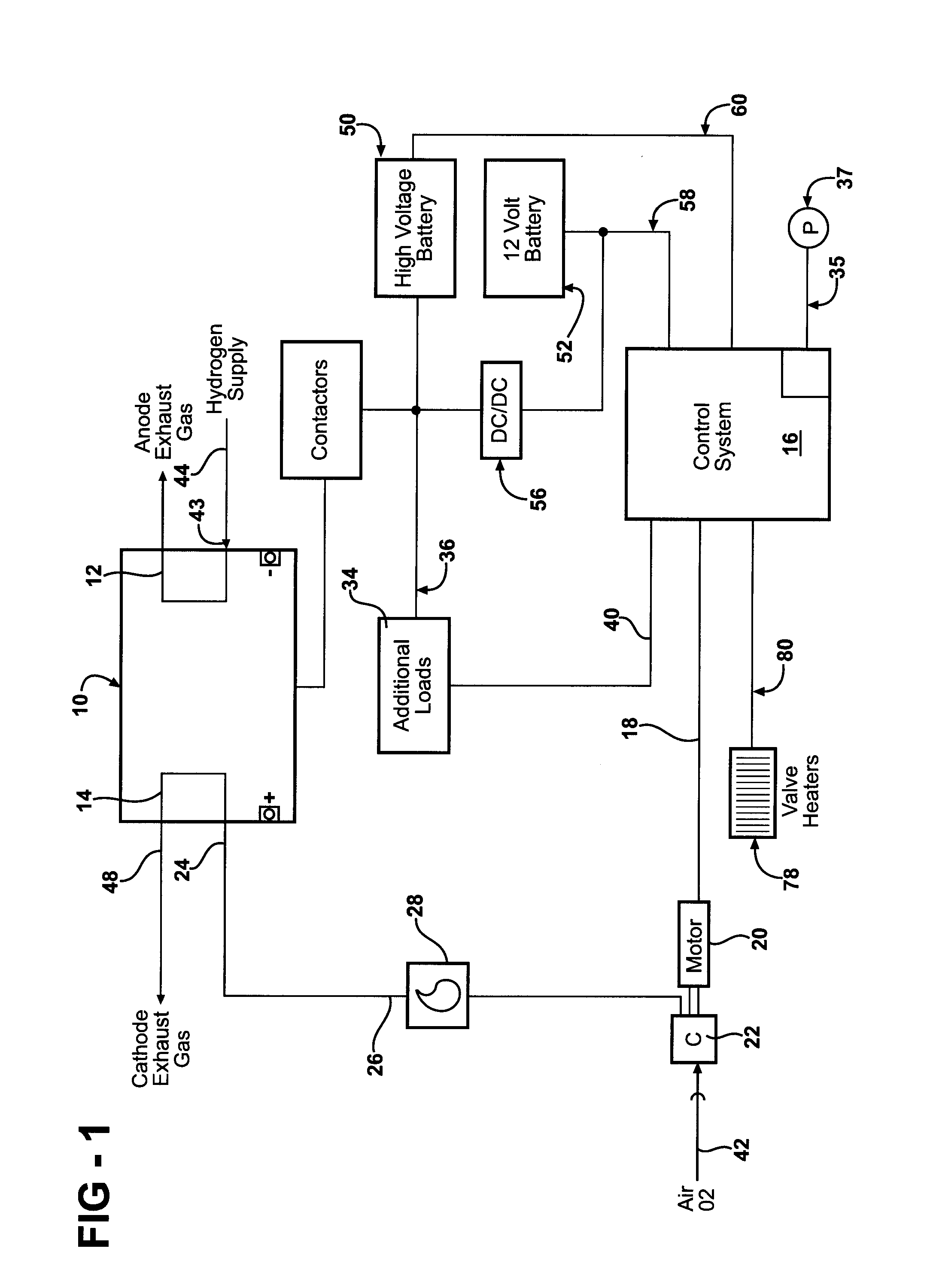
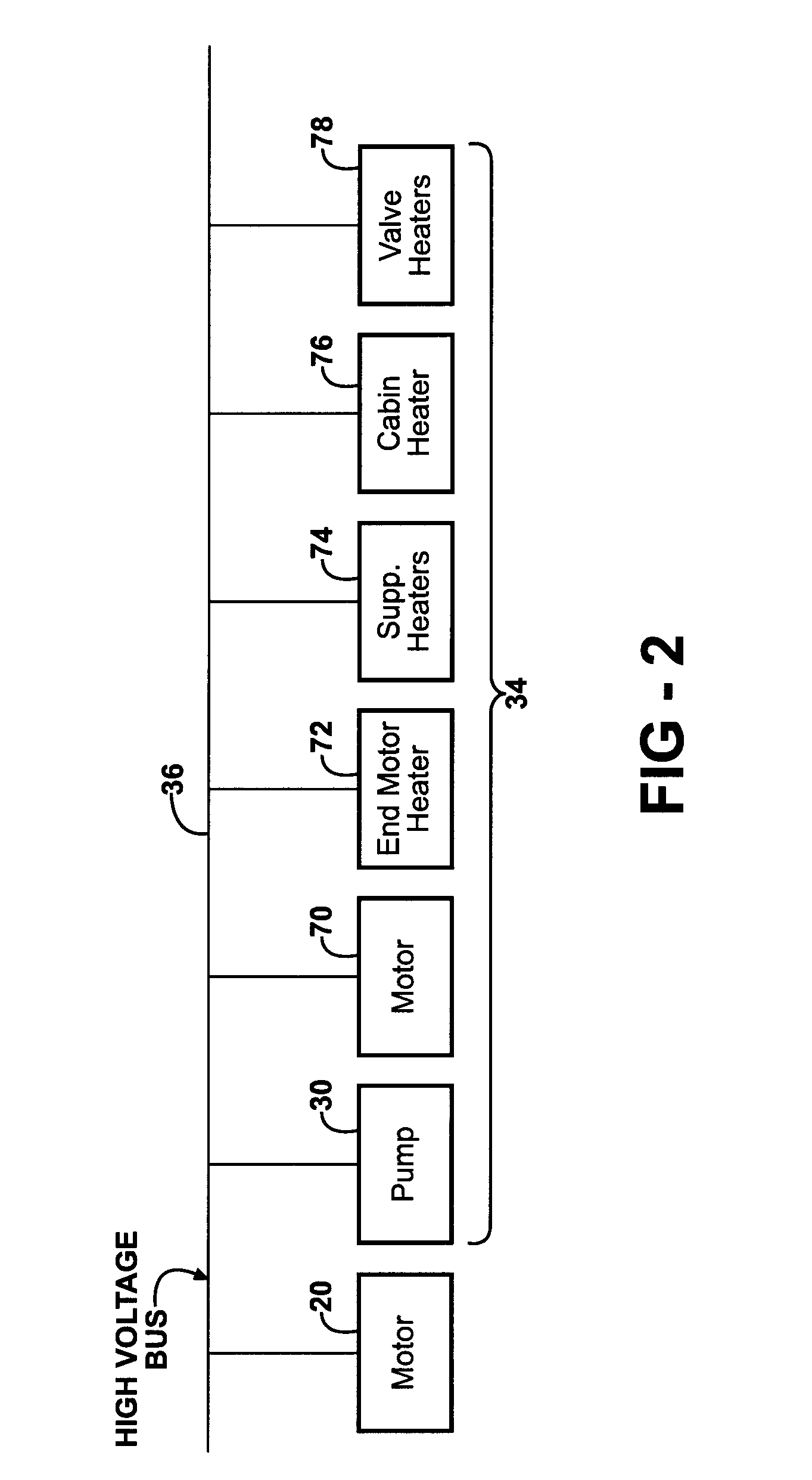
[0013]Referring now to FIG. 1, a basic layout of a fuel cell system with associated components is shown; in practice many variants are possible. A schematic representation of a fuel cell stack 10 integrated into a fuel cell system and consisting of a plurality of individual fuel cells which are connected electrically in series is shown. It is further understood that the individual fuel cells can be connected electrically in parallel without departing from the scope of this invention. The anode sides of all individual fuel cells of the fuel c...


PUM


Abstract

A method for starting a cold or frozen fuel cell stack as efficiently and quickly as possible in a vehicle application is based upon a state of charge of a first power source such as a high voltage battery. Power flow between the first power source and fuel cell system is coordinated in conjunction with a specific load schedule and parallel control algorithms to minimize the start time required and optimize system warm-up.

Description


Claims


Application Information

Patent Timeline
Owner GM GLOBAL TECH OPERATIONS LLC
Why Eureka
Try Eureka