Hydraulic jack with lowering control means

a technology of hydraulic jacks and control means, applied in the field of hydraulic jacks, can solve problems such as operator injuries

Inactive Publication Date: 2008-04-10
LARIN A CALIFORNIA
View PDF6 Cites 30 Cited by
  • Summary
  • Abstract
  • Description
  • Claims
  • Application Information

AI Technical Summary

Problems solved by technology

However, should the hydraulic mechanism used to raise and lower the jack malfunction, then the jack may drop the load too quickly possibly resulting in injury to the operator.

Method used


Image

  • Hydraulic jack with lowering control means
  • Hydraulic jack with lowering control means
  • Hydraulic jack with lowering control means

Examples


Embodiment Construction

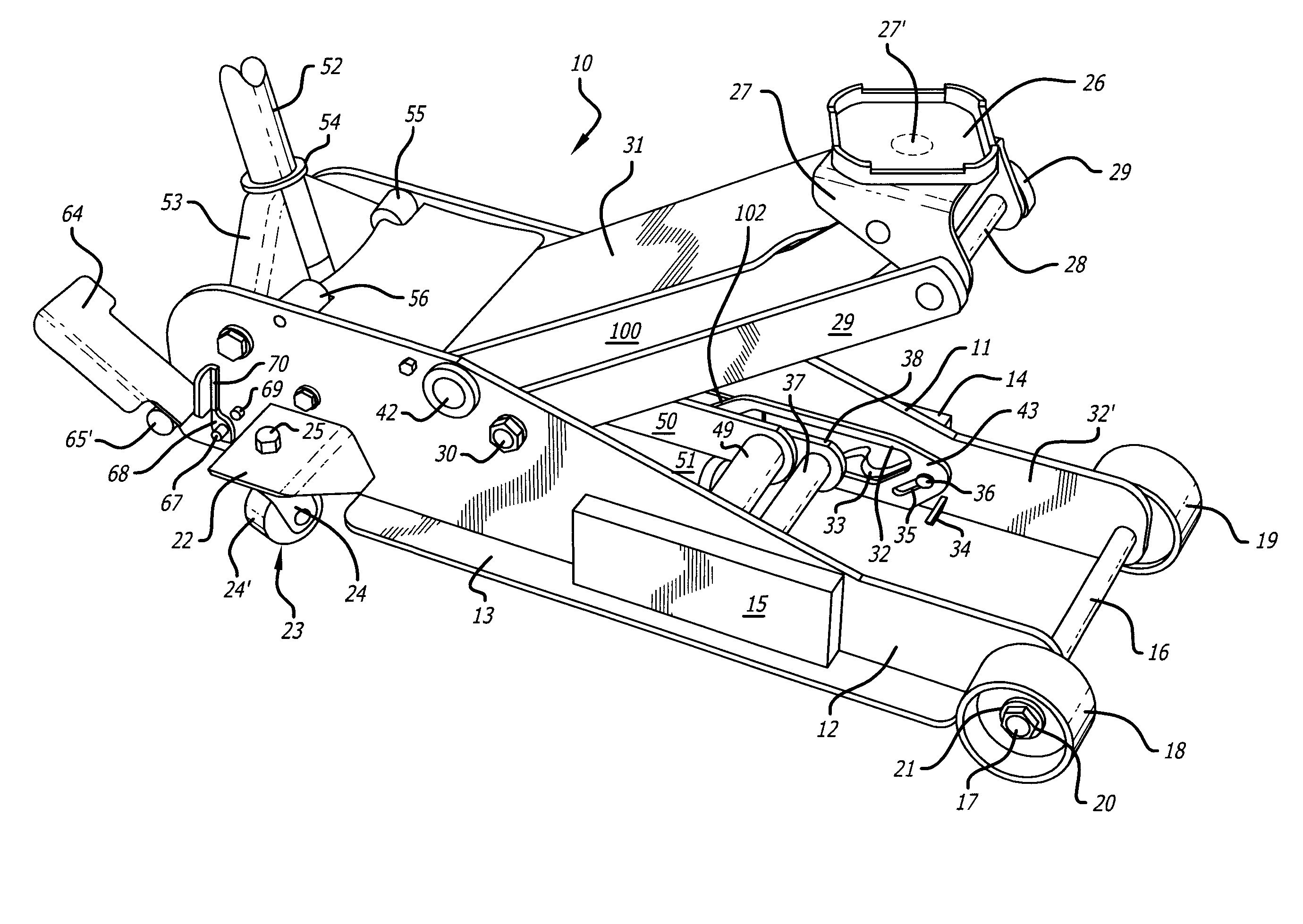
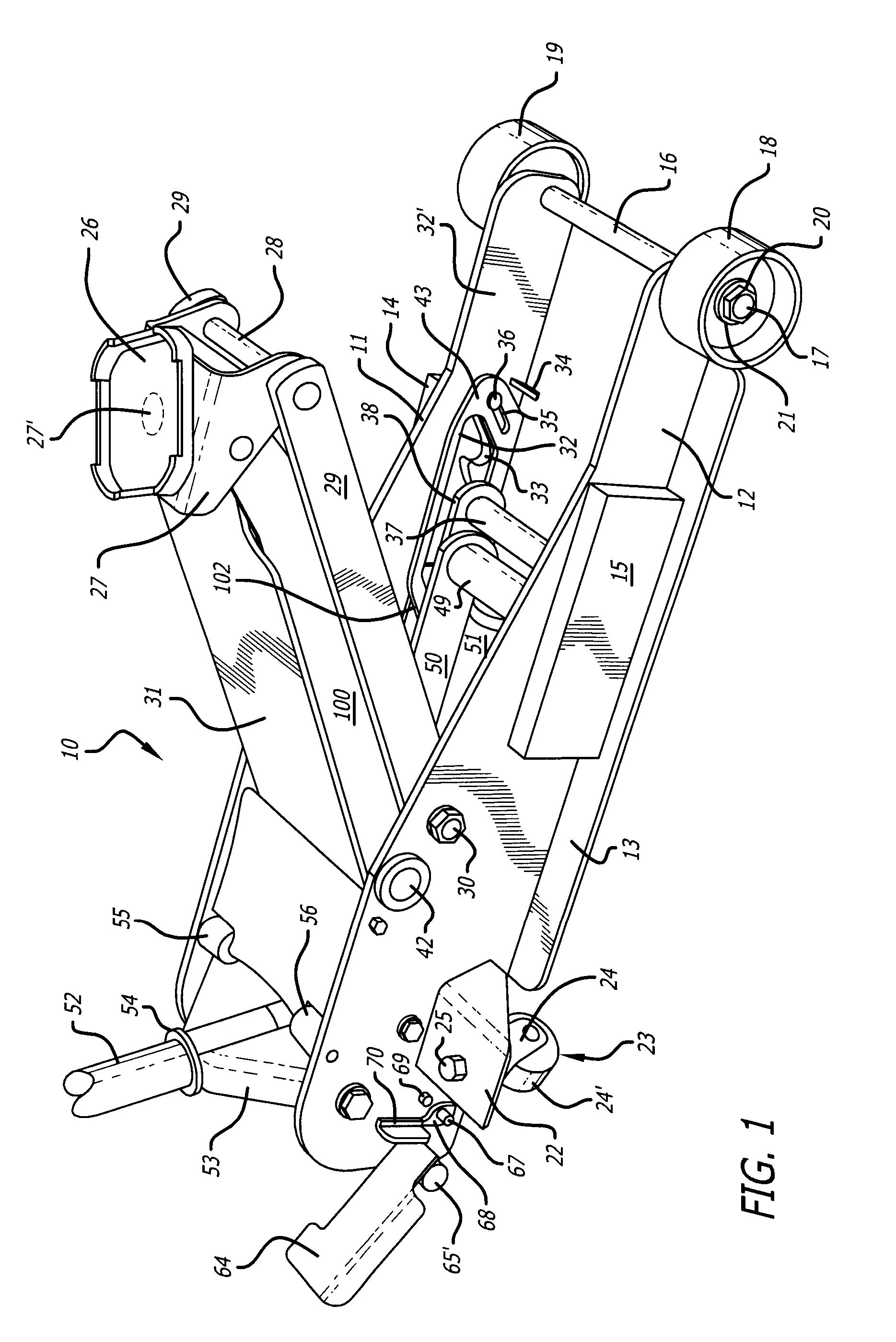
[0013]A jack 10 in accordance with the teachings of the invention is shown in FIG. 1. Jack 10 has a pair of spaced side plates 11, 12 with integral outwardly extending flanges 13 on each side plate 11, 12 (only plate 13 on side plate 12 shown in FIG. 1). Block members 14, 15 may be provided on the outside of each side of plate 11, 12 to add weight and stability to jack 10.

[0014]Front axle 16 extends between plates 11, 12 terminating on the outside of plates 11, 12 in roller ends 17 having wheels 18, 19 rotatably mounted thereon as is well known in the art. Ends 17 are threaded at their terminal ends receiving a suitable nut 20 and washer 21 thereon to retain the wheels 18, 19 in place.

[0015]A pair of L-shaped flanges 22 are provided on side plates 11, 12 at the rear of jack 10. Each flange 22 holds a castor housing 23 comprised of a downwardly extending U-shaped yoke 24 having a wheel 24′ secured to housing 23 by a nut 25.

[0016]A saddle 26 is rotatably mounted to a U-shaped flange 2...


PUM


Abstract

A hydraulic jack comprising a hydraulically actuated saddle movable from a first lowered position to a second raised position, the jack having a handle which, when pumped up and down, hydraulically raises the saddle, lowering control means associated with the jack for preventing premature lowering of the saddle upon malfunction of the hydraulic actuation during raising of the saddle and a release lever engaging the lowering control means adapted to release the same and permit lowering of the saddle when the handle is pumped up and down.

Description

BACKGROUND[0001]1. Field[0002]This disclosure relates to relates to hydraulic jacks; and, more particularly, to hydraulic jacks that are used to raise and lower loads.[0003]2. General Background[0004]Hydraulic jacks used to raise and lower loads are well known in the art. Such jacks are usually rolled or otherwise placed under a load that it is desired to lift, such as a vehicle, then a lever is activated to raise the saddle of the jack that engages the load placed thereon. When it is desired to lower the load, the lever is used to release the jack and lower the saddle and thus the load placed thereon. However, should the hydraulic mechanism used to raise and lower the jack malfunction, then the jack may drop the load too quickly possibly resulting in injury to the operator.[0005]There is need for an hydraulic jack that has lowering control means for preventing the jack from being lowered out of control while lifting the load placed thereon due to malfunction or the like.SUMMARY[000...

Claims


Application Information

Patent Timeline
Patent Type & Authority Applications(United States)
IPC IPC(8): B60P1/48
CPCB66F5/04
Inventor FANG, XIANGZHANG, ALLEN SHOUYUN
Owner LARIN A CALIFORNIA
Why Eureka
Try Eureka