Chipless RFID tag and method for communicating with the RFID tag

a technology of rfid tags and chips, applied in the direction of instruments, mechanical actuation of burglar alarms, near-field systems using receivers, etc., can solve the problems of limited magnetic strips can be read, and the effective range at which barcodes can be reliably read is typically not better than a few centimeters

Inactive Publication Date: 2008-04-10
IBM CORP
View PDF7 Cites 19 Cited by
  • Summary
  • Abstract
  • Description
  • Claims
  • Application Information

AI Technical Summary

Problems solved by technology

Barcodes and magnetic strips are limited, however, by the relatively small amount of data they can encode and the effective range at which they can be read, which is quite short.
Similarly, the effective range at which barcodes can be reliably read is typically not better than a few centimeters.
In addition to range limitations, both barcodes and magnetic strips are impossible to read if there is any obstruction between the reading device and the barcode or magnetic strip.
When reading a magnetic strip or barcode, the orientation of the reading device relative to the barcode or magnetic strip also presents a problem.
If the reading device is not properly aligned or is held at an incorrect angle, the encoded information cannot be read.
As a result of these problems, each individual read operation requires manual scanning by a human operator if high read accuracy is needed.
However, their inherent limitations have prevented their use in a wide range of applications for machine readable text where highly reliable and totally automated reading is required for read ranges of up to several meters.
There is a radical difference in cost and performance between these two types; to such an extent, in fact, that they rarely compete with one another as to the appropriate type of use.
As a general rule, chipped tags cost more but have a larger data capacity than chipless tags.
Although chipped tags do have a longer range than magnetic strip and barcode systems, the range at which th

Method used


Image

  • Chipless RFID tag and method for communicating with the RFID tag
  • Chipless RFID tag and method for communicating with the RFID tag
  • Chipless RFID tag and method for communicating with the RFID tag

Examples


Embodiment Construction

[0041]The present invention is directed to a RFID tag, a method, a computer program and to an interrogator.

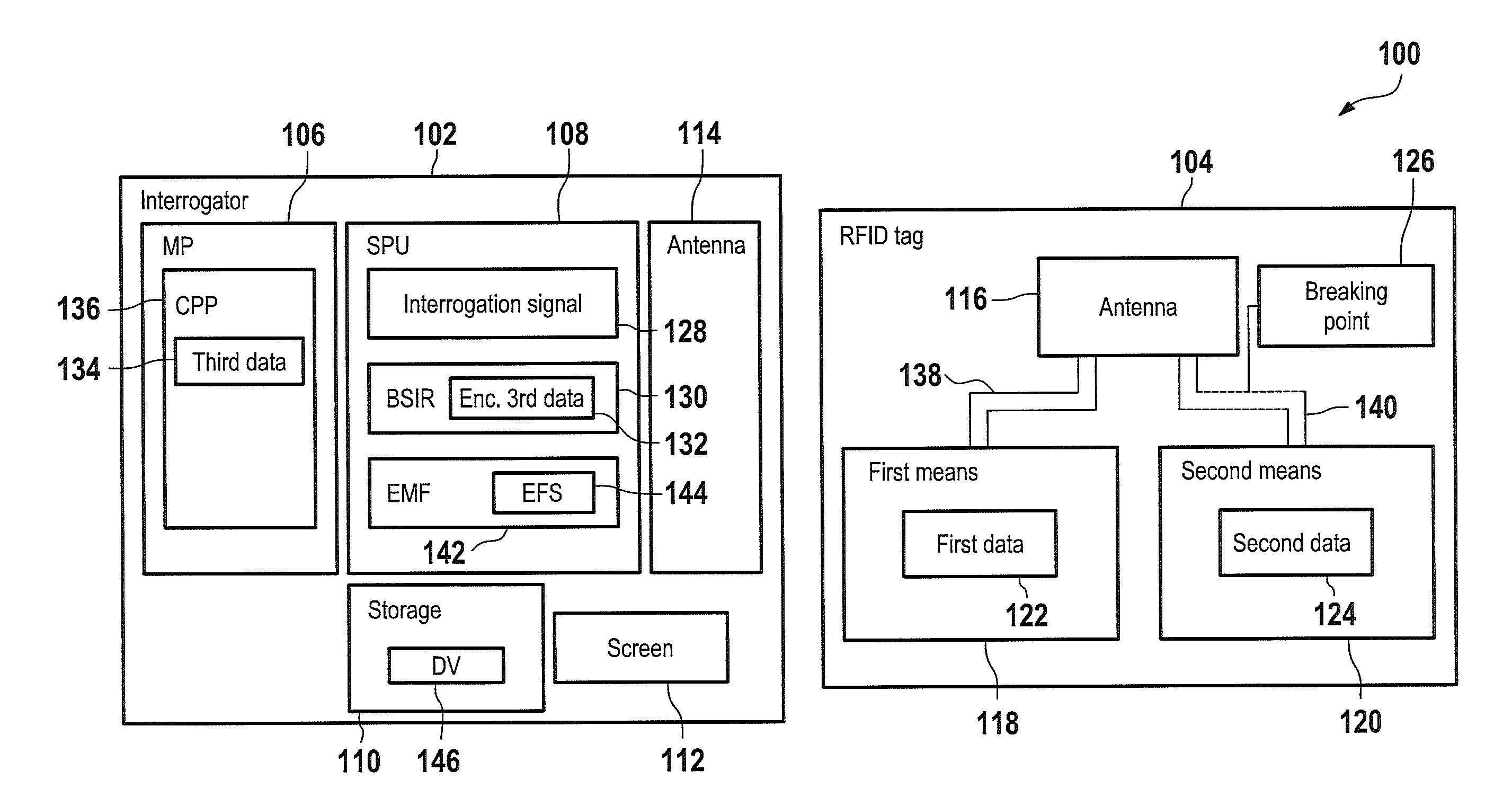
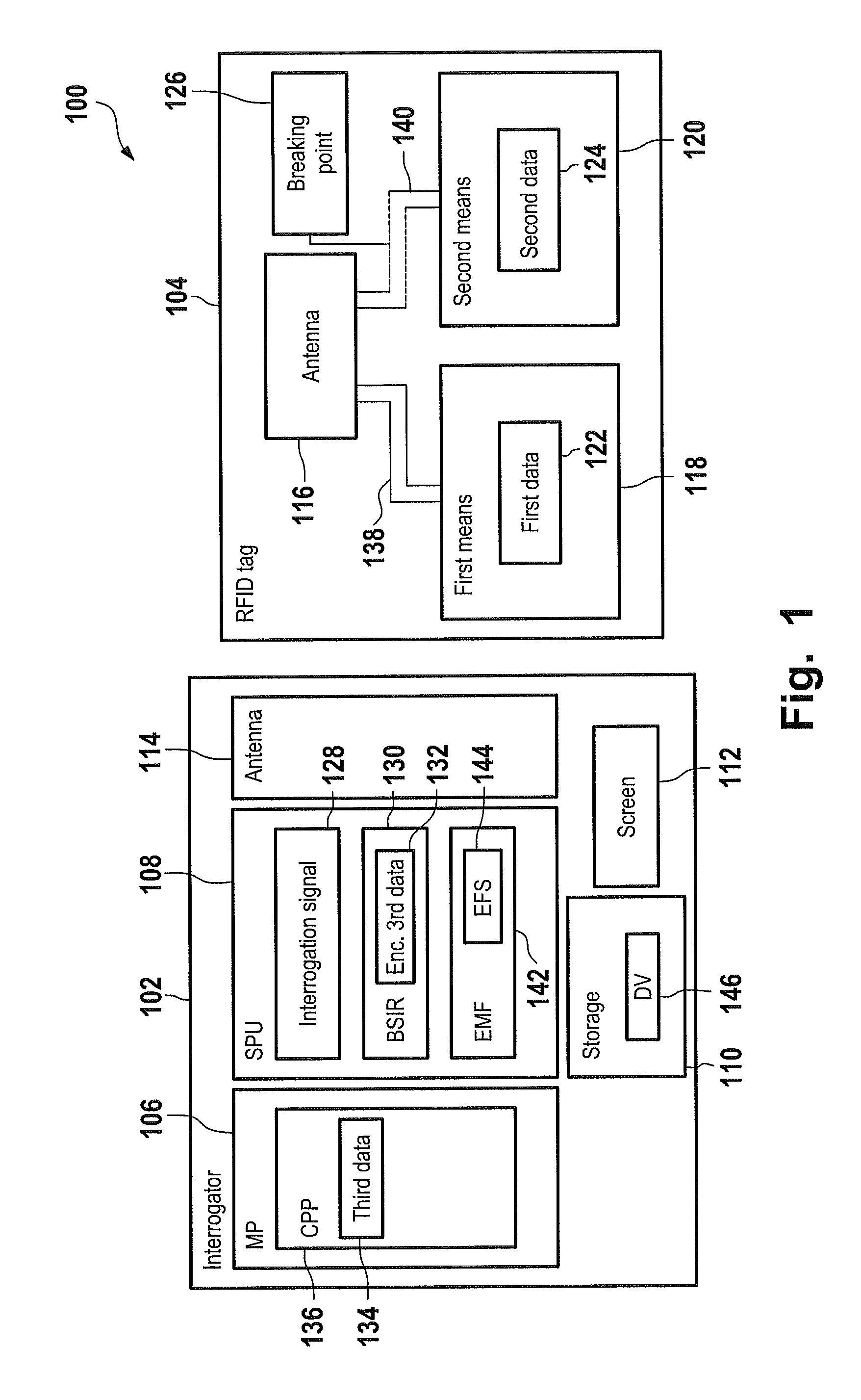
[0042]In accordance with an embodiment of the invention, there is provided a RFID tag comprising an antenna, first means for storing first data, and second means for storing second data. The first means and the second means are electrically connected in parallel to the antenna and the second data is complementary to the first data.

[0043]The first storage means hold first data which is the data of interest and which is to be interrogated by use of a radio frequency signal via an interrogator. The first data can, e.g., correspond to an identifier or a code. However, as the second data is complementary to the first data and as both the first and the second storage means are connected to the antenna, the RFID tag responds with a signal that corresponds to the combination of the first and second data. Hence the RFID tag does not disclose the first data when interrogated as long as t...


PUM


Abstract

A radio frequency identification (RFID) tag and a method and system for communicating with the RFID tag. The RFID tag includes a first and second structure respectively holding first data and second data that is complementary to the first data. The RFID tag does not include a microchip. An electromagnetic radio frequency signal is transmitted from an interrogator to the RFID tag. The interrogator receives, from the RFID tag, a response signal including third data being the first data or a combination of the first data and the second data. The interrogator extracts the third data from the response signal. A default value equal to the combination of the first data and the second data is stored in the interrogator. If the interrogator determines that the third data is unequal/equal to the default value, then a screen of the interrogator displays that the RFID tag is enabled/not enabled.

Description

FIELD OF THE INVENTION[0001]The invention relates to a chipless RFID tag and to a method for communicating with the RFID tag.BACKGROUND OF THE INVENTION[0002]Modern technology has produced a number of useful electronic identification methods and devices. Most familiar are the ubiquitous barcodes and magnetic strips that, together with their readers, are widely employed by businesses and others to perform several identification functions. The main reason barcodes and magnetic strips are so widely used is that they are very cheap.[0003]Barcodes and magnetic strips are limited, however, by the relatively small amount of data they can encode and the effective range at which they can be read, which is quite short. Magnetic strips, for example, generally have such a limited range that the reader must be in direct contact with the strip in order to decode the data thereon. In the very few cases that a magnetic strip is read with a device other than a direct contact reader, the effective re...

Claims


Application Information

Patent Timeline
IPC IPC(8): H04B7/00
CPCG06K19/0672G06K19/07758H04B5/0031H04B5/02H04B5/0056H04B5/0062H04B5/0037
Inventor BAUCHOT, FREDERICCLEMENT, JEAN-YVESMARMIGERE, GERARDSECONDO, PIERRE
Owner IBM CORP
Why Eureka
Try Eureka