Axle end equipment for a vehicle, in particular an aircraft

a technology for aircraft and end equipment, applied in the direction of instruments, devices using electric/magnetic means, transportation and packaging, etc., can solve the problems of pressure sensor and the connection between the rotary portion and the pressure sensor running the risk of damage, and achieve the effect of any risk of damag

Inactive Publication Date: 2008-04-10
SAGEM DEFENSE SECURITE SA
View PDF4 Cites 16 Cited by
  • Summary
  • Abstract
  • Description
  • Claims
  • Application Information

AI Technical Summary

Benefits of technology

[0007]It is thus possible to remove the rotary portion without worrying about the sensor, which, since it has no mechanical or electrical connection with the rotary portion, can be left on the wheel without any risk of damage.

Problems solved by technology

When the wheel is removed, the operator must disassemble the rotary portion and the pressure sensor, and as a result the pressure sensor and the connection between the rotary portion and the pressure sensor run the risk of being damaged.

Method used


Image

  • Axle end equipment for a vehicle, in particular an aircraft
  • Axle end equipment for a vehicle, in particular an aircraft
  • Axle end equipment for a vehicle, in particular an aircraft

Examples


first embodiment

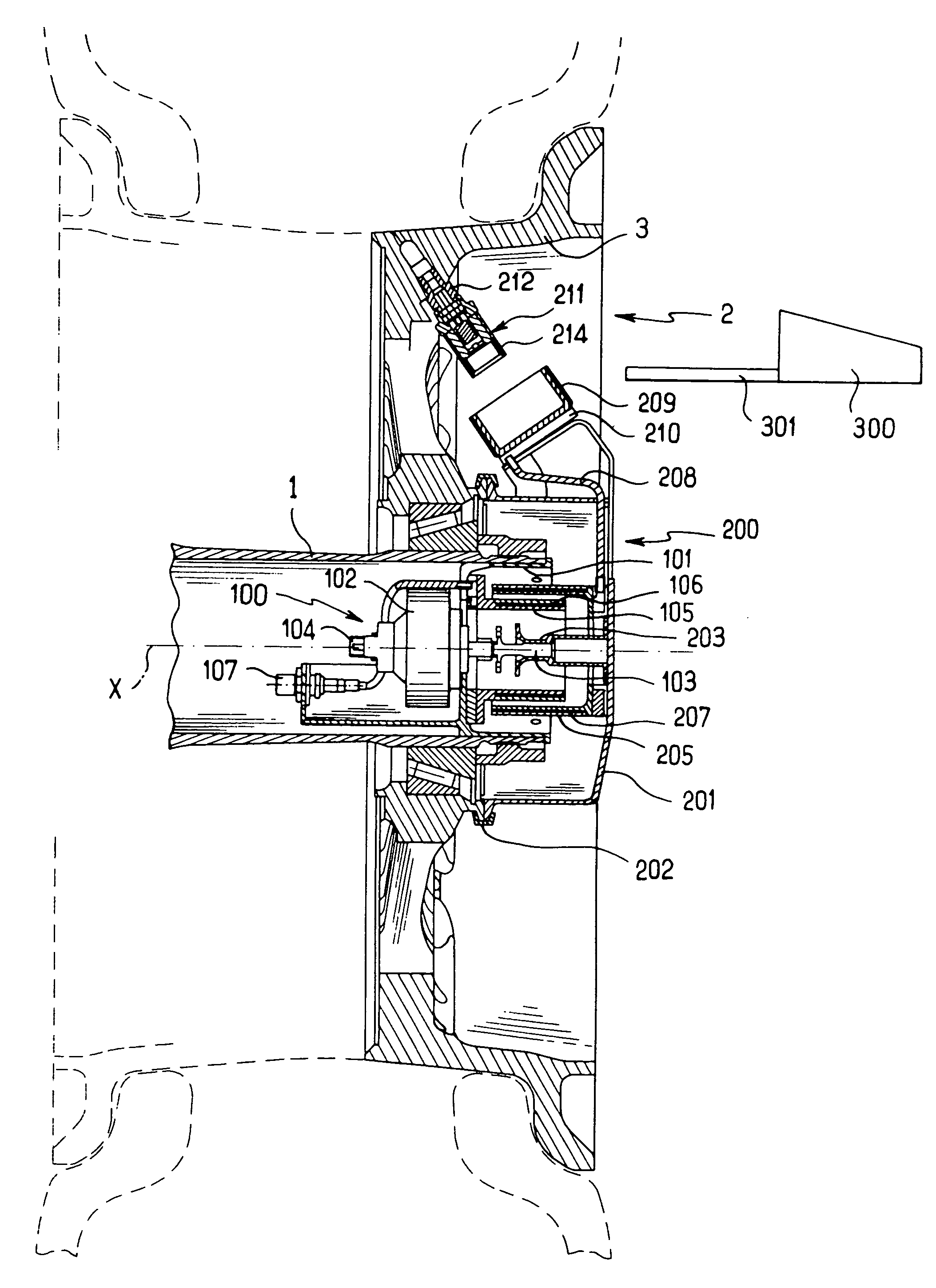
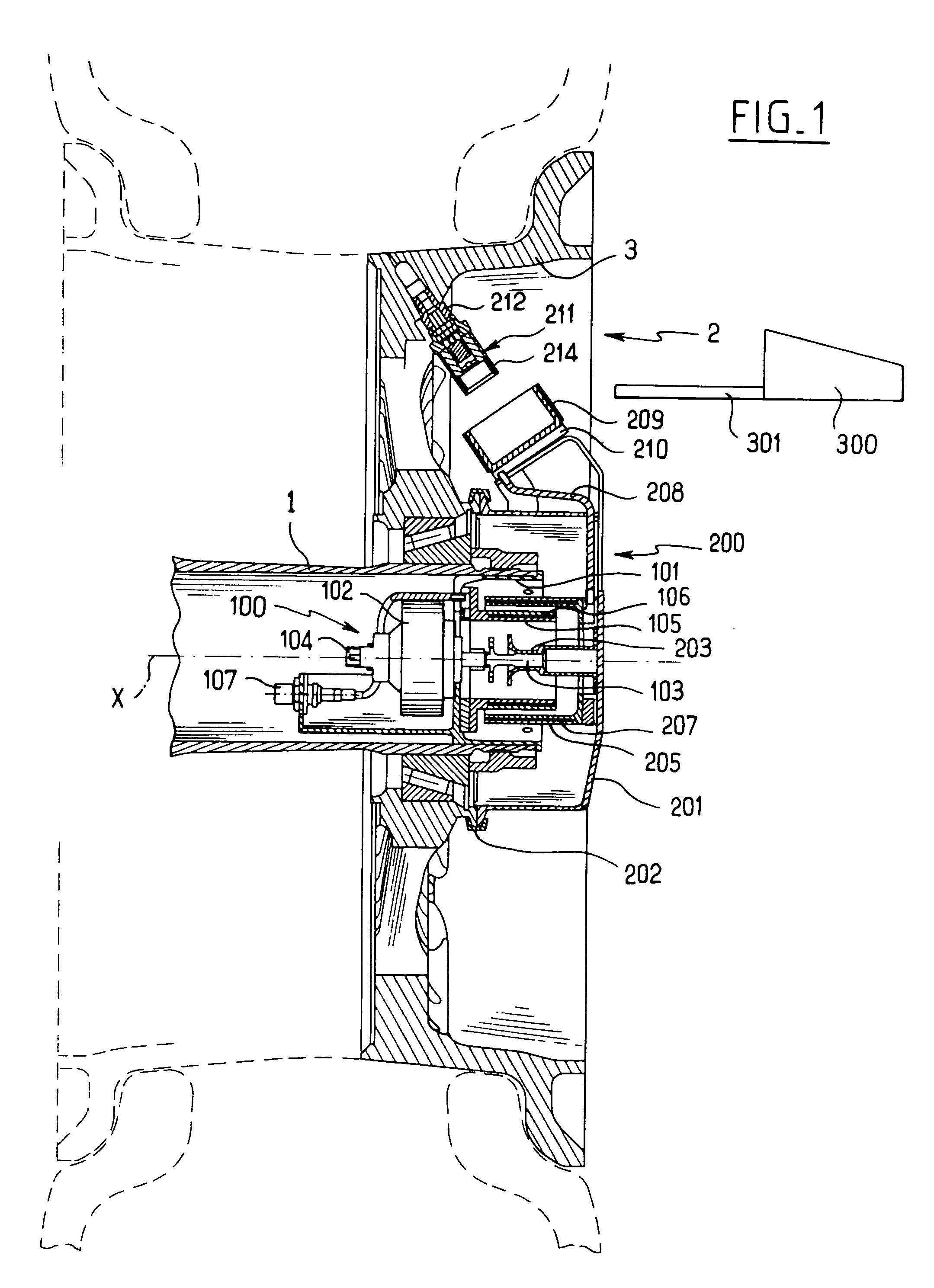
[0017]In a first embodiment shown in FIGS. 1 and 2, the equipment of the invention is associated with an axle end 1 carrying a wheel 2 of which one half-rim 3 can be seen (the other half-rim being silhouetted as a dashed line).

[0018]The equipment shown serves to measure continuously the speed of rotation of the wheel 2 and also the pressure that exists in the tire mounted on the wheel 2 (shown in dashed-line outline).

[0019]For this purpose, the equipment comprises a stationary portion 100 comprising a sleeve 101 inserted in the axle 1 and carrying a tachometer 102 having a shaft 103 that extends along the axis of rotation X of the wheel 2.

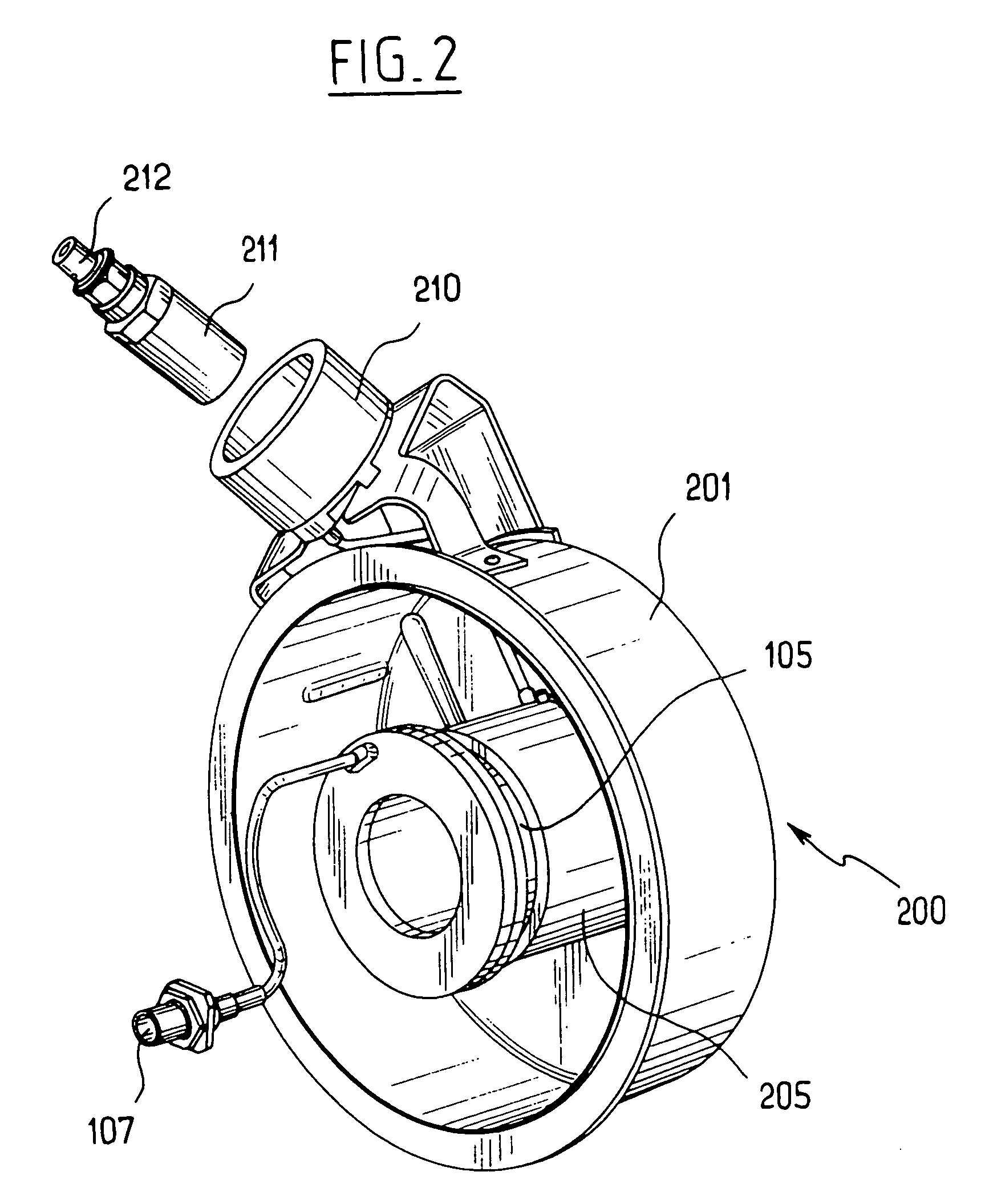
[0020]The equipment also comprises a rotary portion 200 comprising a cap 201 secured to the half-rim 3 by a clamping collar 202. The cap 201 carries internally a driver 203 adapted to co-operate with the shaft 103 of the tachometer 102 in order to drive said shaft in rotation when the wheel 2 is rotating. The tachometer 102 includes a first connect...

fourth embodiment

[0048]In a fourth embodiment shown in FIGS. 7 and 8 and that does not include a tachometer, the fourth antenna 214 is no longer secured directly to the pressure sensor 211 but is offset so as to be closer to the cap 201 of the rotary portion 200.

[0049]For this purpose, the pressure sensor 211 is associated with a carrier member 220 having two branches that extend against the flanks of spokes of the half-rim 3 of the wheel 2, matching the shape of the gaps between the spokes. The ends of the branches meet in order to receive the fourth antenna 214 which is thus located close to the cap 201 of the rotary portion 200. The carrier member 220 is designed to be lightly forced between the spokes of the half-rim 3, so as to avoid any vibration of the fourth antenna 214.

[0050]The carrier member 220 houses connection wires between the pressure sensor 211 and the fourth antenna 214, so as to ensure that the wires are protected from impacts.

[0051]The third antenna 209 is carried by a projection...


PUM


Abstract

The invention relates to axle end equipment for a vehicle, in particular an aircraft, the equipment comprising a stationary portion for securing to the axle and a rotary portion for securing to the wheel carried by the axle. According to the invention, the rotary portion comprises first remote connection means in communication with a sensor mounted on the wheel so as to put the sensor and the rotary portion of the equipment into contactless electromagnetic relationship.

Description

[0001]The invention relates to axle end equipment for a vehicle, in particular an aircraft.BACKGROUND OF THE INVENTION[0002]Axle end equipments for vehicles, in particular aircraft, are known that comprise a stationary portion for being placed in the axle and a rotary portion for being secured to a wheel carried by the axle.[0003]For example, such equipment may include a tachometer for measuring the speed of rotation of the wheel, and a pressure sensor for measuring the pressure that exists in a tire fitted to the wheel.[0004]The pressure sensor is connected by a cable to the rotary portion. When the wheel is removed, the operator must disassemble the rotary portion and the pressure sensor, and as a result the pressure sensor and the connection between the rotary portion and the pressure sensor run the risk of being damaged.OBJECT OF THE INVENTION[0005]An object of the invention is to provide equipment that does not present the above-specified drawback.BRIEF DESCRIPTION OF THE INVEN...

Claims


Application Information

Patent Timeline
Patent Type & Authority Applications(United States)
IPC IPC(8): G08B21/00
CPCB60C23/0413G01P3/44B60C23/043B60C2200/02
Inventor PRADIER, JEAN-CLAIREVENOR, ERICLAVAUD, THOMASMAES, BERTRAND
Owner SAGEM DEFENSE SECURITE SA
Why Eureka
Try Eureka