
Eureka
For R&D, Eureka makes reading and utilizing patents & technical documents easy.
Eureka AIR
Designed for self-driven R&D workflows. Generate viable solutions, solve complex R&D challenges, empower your innovation with AI.

Eureka Materials
Designed for material experts only. Revolutionize your material R&D, from search, analyze, to developing new materials.

TechResearch
Generate reliable direction feasibility study reports for your R&D in just a few steps.

TechSeek
Discover and master advanced knowledge NOW. Basics, ideas, possibilities, all at once.

TechMind
As an expert in R&D Theories, TechMind can generates customized viable solutions instantly.

TechRisk
Analyze your overall solution with one click, know your potential R&D risks in advance.

TechMonitor
Get weekly tech updates, stay abreast of the latest tech innovations and key insights.
Active Mirror for Power Beaming
- Summary
- Abstract
- Description
- Claims
- Application Information
AI Technical Summary
Benefits of technology
Problems solved by technology
Method used
Image

Examples
Embodiment Construction
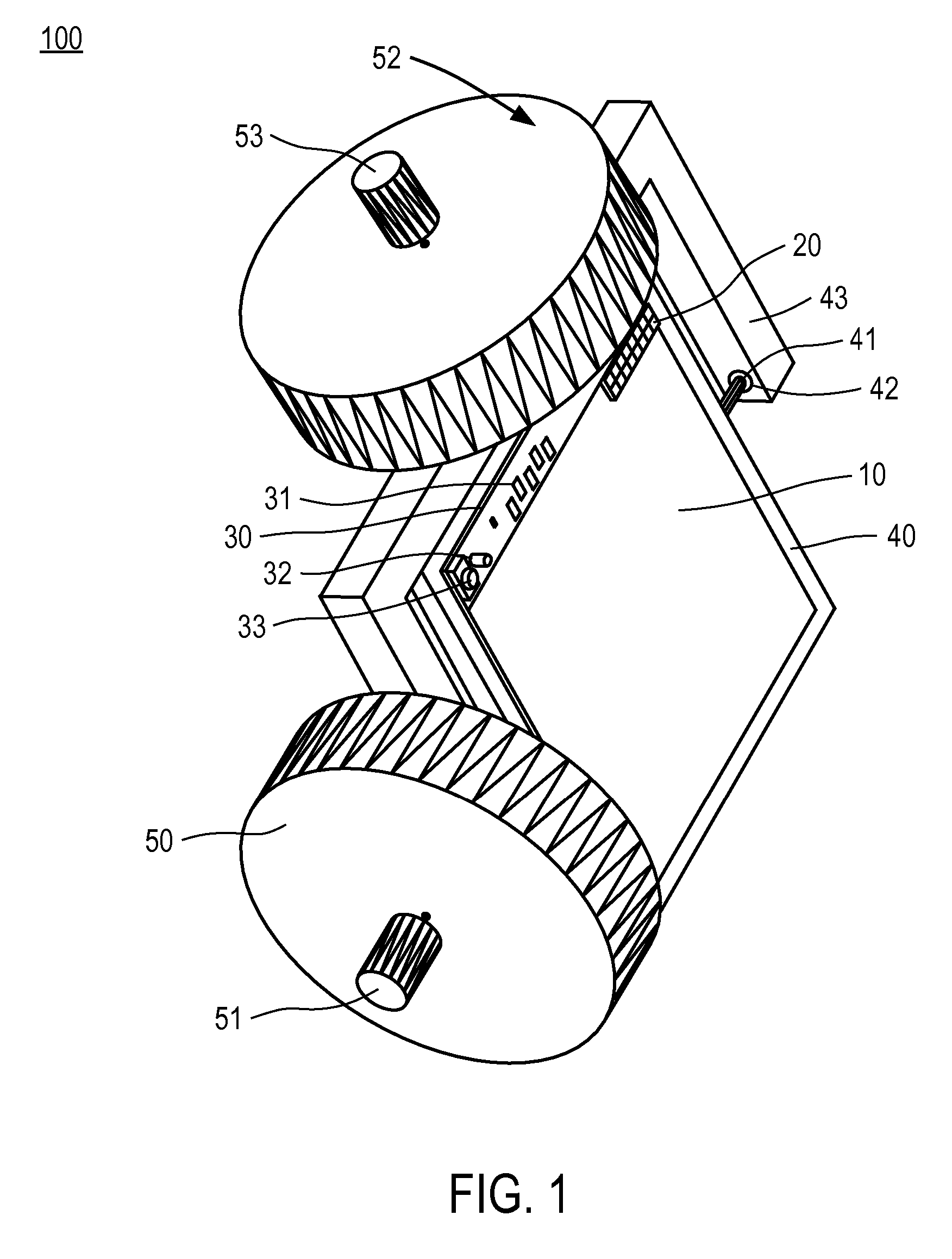
[0013]FIG. 1 illustrates a mirror assembly 100 for power beaming, in accordance with one embodiment. The mirror assembly 100 includes a reflective surface 10 supported by a case 40.
[0014] The reflective surface 10 can be a standard optical mirror, such as mirrors sold by Thorlabs, Inc., of Newton, N.J. The choice of the mirror material can depend on the wavelength of light in the power beam. Preferably, the mirror should be constructed from a material that reflects efficiently at the wavelength transmitted by the power beaming system. The size of the mirror can depend on the size of the power beam. For example, if the cross-section of the power beam is exactly round, one inch in diameter, and the mirror is to be used at up to 45 degrees to the power beam, in one embodiment, the mirror should be at least 1.414 inches in diameter to reflect the entire cross section of the power beam.
[0015] The case 40 mechanically supports the reflective surface 10. An injection molded case is a nor...
PUM
 Abstract
Description
Claims
Application Information
 - R&D Engineer
- R&D Manager
- IP Professional
- Industry Leading Data Capabilities
- Powerful AI technology
- Patent DNA Extraction
Browse by: Latest US Patents, China's latest patents, Technical Efficacy Thesaurus, Application Domain, Technology Topic, Popular Technical Reports.
© 2024 PatSnap. All rights reserved.Legal|Privacy policy|Modern Slavery Act Transparency Statement|Sitemap|About US| Contact US: help@patsnap.com