Nozzle assembly having subsidiary brush unit

a technology of nozzle assembly and nozzle assembly, which is applied in the direction of vacuum cleaners, cleaning equipment, domestic applications, etc., can solve the problems of inability to easily separate dirt from the surface to be cleaned, weak cradling strength of nozzle assembly, etc., and achieve the effect of efficient cleaning of dir

Active Publication Date: 2008-04-17
SAMSUNG ELECTRONICS CO LTD
View PDF8 Cites 18 Cited by
  • Summary
  • Abstract
  • Description
  • Claims
  • Application Information

AI Technical Summary

Benefits of technology

[0012]In accordance with an aspect of the present disclosure, a nozzle assembly of a vacuum cleaner includes a nozzle assembly body; a drum brush unit disposed in the nozzle assembly body, and having a drum brush disposed to brush away dirt or dust adhered to a surface to be cleaned while coming in rotation contact therewith; and a subsidiary brush unit disposed to the nozzle assembly body or the dru

Problems solved by technology

However, dirt, such as hair, fur or the like, which is firmly stuck to the surface to be cleaned, particularly, a surface of carpet, is not separated therefrom well only by the drum brush.
Although the drum brush strikes or scrapes against the surface to be cleaned while rotating, scraping strength thereof is too weak to separate the dirt from the surface to be cl

Method used


Image

  • Nozzle assembly having subsidiary brush unit
  • Nozzle assembly having subsidiary brush unit
  • Nozzle assembly having subsidiary brush unit

Examples


first embodiment

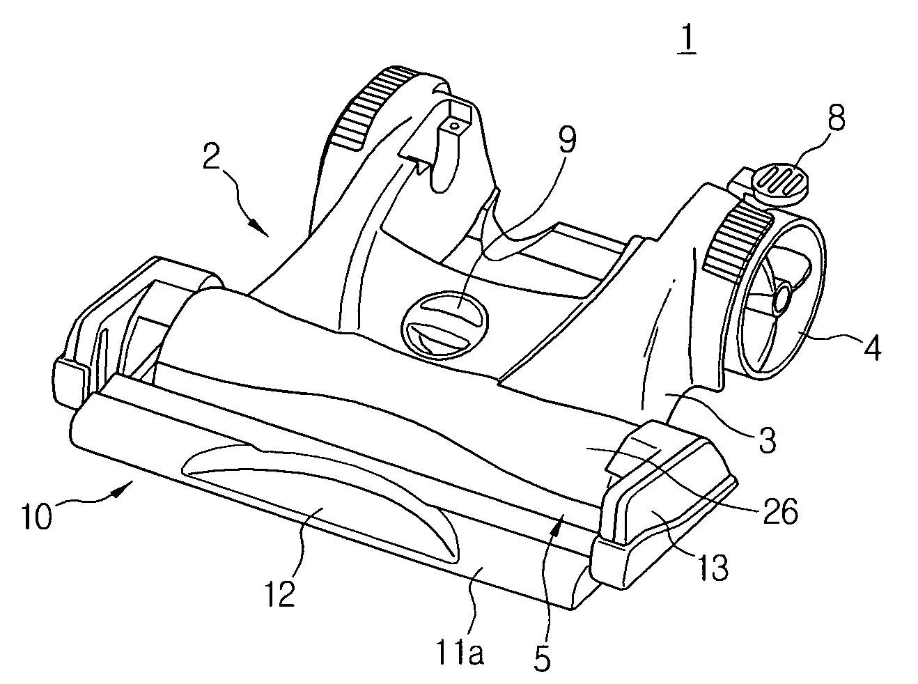
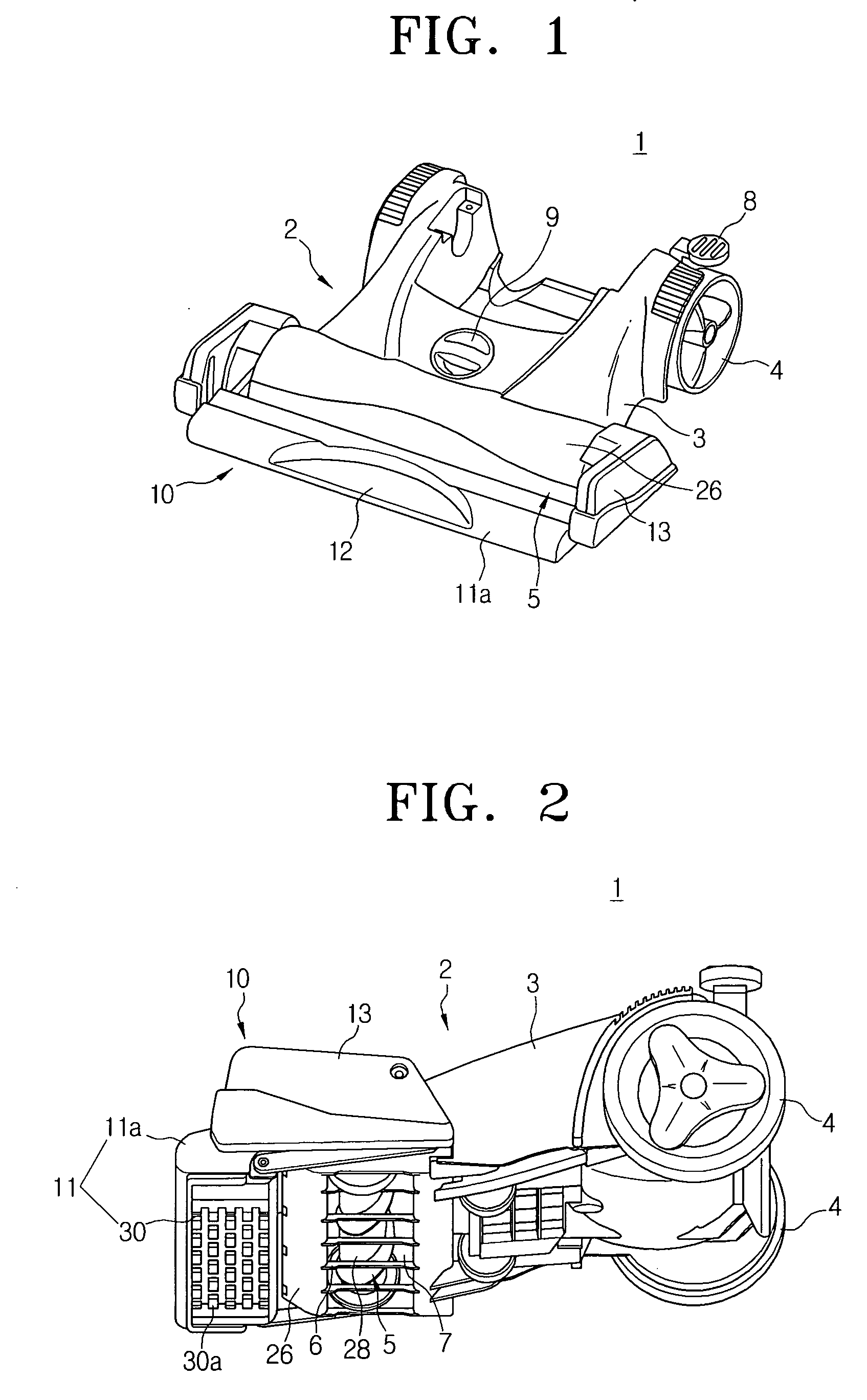
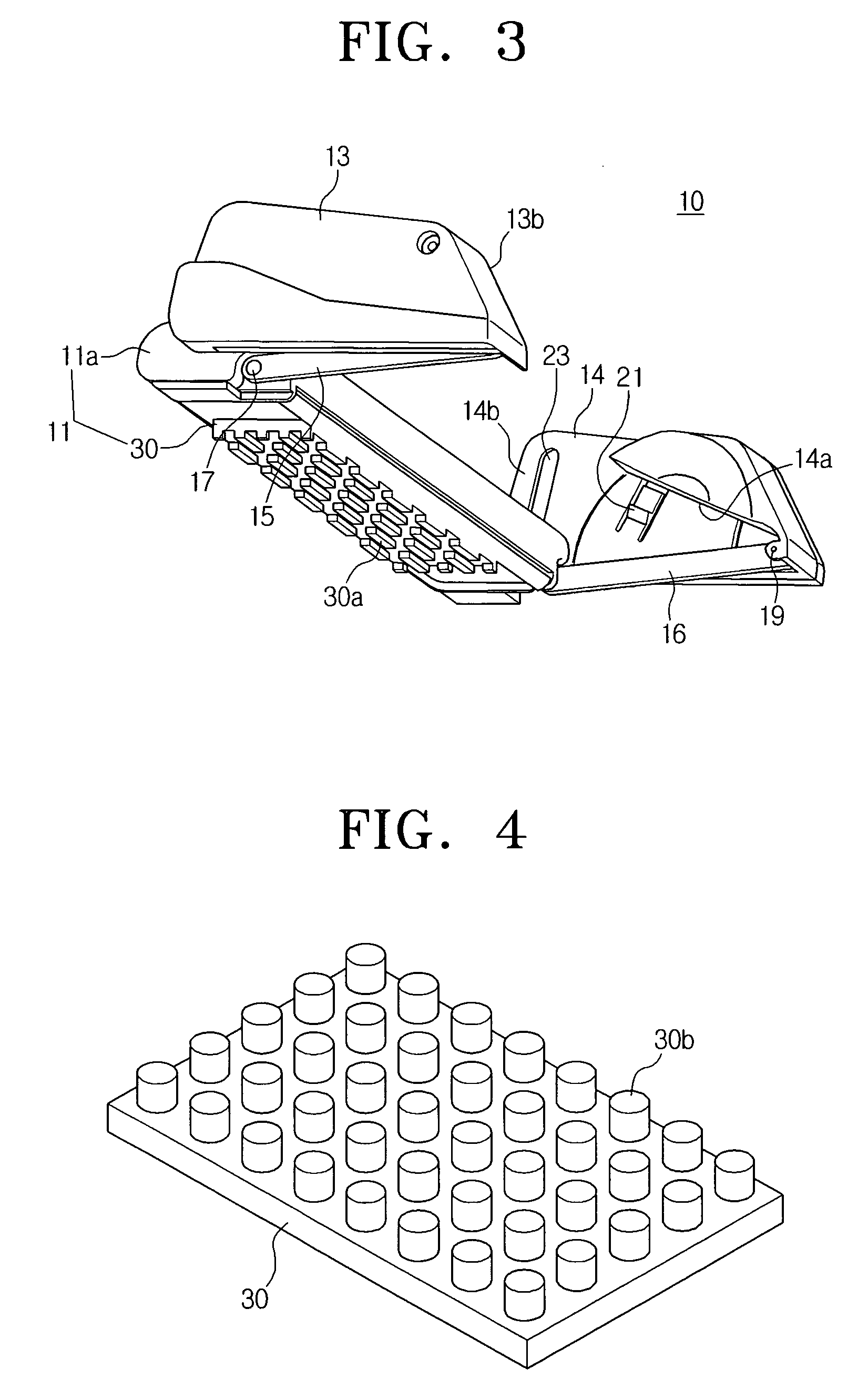
[0067]Referring to FIGS. 1 through 3, there is illustrated a nozzle assembly 1 according to a first exemplary embodiment of the present disclosure. The nozzle assembly 1 includes a nozzle assembly body 2, a drum brush unit 5 and a subsidiary brush unit 10.

[0068]The nozzle assembly body 2 includes a body casing 3. The body casing 3 has an air passage (not illustrated), which is connected to a dust inlet 7 (see FIG. 2) formed in the drum brush unit 5. Accordingly, when a vacuum motor (not illustrated) mounted in a cleaner body (not illustrated) generates a suction force, dust or dirt along with air is drawn in through the dust inlet 7, and flows into the cleaner body in the rear of the nozzle assembly body 2 via the air passage of the nozzle assembly body 2. In addition, a turbine, which is rotated by the drawn-in air, or a driving motor (not illustrated), which drives a drum brush 28, can be disposed in the body casing 3. To easily move the nozzle assembly 1, a pair of wheels 4 is in...

second embodiment

[0089]FIG. 12 is a perspective view exemplifying a nozzle assembly 1′ of a vacuum cleaner according to a second exemplary embodiment of the present disclosure, and FIG. 13 is a perspective view exemplifying the nozzle assembly 1′ illustrated in FIG. 12 from which an upper casing 132 of a subsidiary brush unit 110 are removed and in which left and right bracket parts 180 are partially cut away, so that a lower casing 140 and a frame member 150 are shown in detail.

[0090]Referring to FIGS. 12 and 13, the nozzle assembly 1′ according to the second exemplary embodiment of the present disclosure includes a nozzle assembly body 2, a drum brush unit 5, left and right bracket parts 80, cam members 170, first elastic members 172, and a subsidiary brush unit 110. Here, since constructions of the nozzle assembly body 2 and the drum brush unit 5 are the same as those of the nozzle assembly 1 of the first embodiment, detailed descriptions thereof will be omitted.

[0091]The left and right bracket p...

third embodiment

[0102]FIGS. 19 through 23 are views exemplifying a nozzle assembly 1″ of a vacuum cleaner according to a third exemplary embodiment of the present disclosure.

[0103]Referring to FIG. 19, the nozzle assembly 1″ of the third exemplary embodiment includes a nozzle assembly body 2, a drum brush unit 5, left and right brackets 240, a locking unit 260, and a subsidiary brush unit 210. Here, since constructions of the nozzle assembly body 2 and the drum brush unit 5 are the same as those of the nozzle assemblies 1 and 1′ of the first and the second exemplary embodiments, detailed description thereof will be omitted.

[0104]The drum brush casing 26 has two sliding rails 226 (see FIG. 23) disposed on both sides in front thereof, and a mounting space 221 (see FIG. 20) disposed in the middle in front thereof. In the sliding rails 226 are mounted the left and right brackets 240, respectively, and in the mounting space 221 is installed a locking member 260. As illustrated in FIG. 21, the sliding ra...


PUM


Abstract

A nozzle assembly of a vacuum cleaner capable of easily separating spidery dirt, such as hair, fur of a pet and the like, from a surface to be cleaned is disclosed. The nozzle assembly includes a nozzle assembly body; a drum brush unit disposed in the nozzle assembly body, and having a drum brush disposed to brush away dirt or dust adhered to a surface to be cleaned while coming in rotation contact therewith; and a subsidiary brush unit disposed to one of the nozzle assembly body and the drum brush unit, and having a subsidiary brush to preliminarily brush away the dust or dirt adhered to the surface to be cleaned.

Description

CROSS-REFERENCE TO RELATED APPLICATIONS[0001]This application claims the benefit under 35 U.S.C. §119(e) of U.S. Provisional Patent Application Nos. 60 / 850736, 60 / 850895, 60 / 875,898, and 60 / 919,253, filed Oct. 11, 2006, Oct. 11, 2006, Dec. 20, 2006, and Mar. 21, 2007, respectively, in the United States Patent and Trademark Office, and claims the benefit under 35 U.S.C. §119(a) of Korean Patent Application Nos. 10-2006-0128520, 10-2006-0128522, 10-2007-0015589, 10-2007-0044275, filed on Dec. 15, 2006, Dec. 15, 2006, Feb. 14, 2007, and May 7, 2007, respectively, in the Korean Intellectual Property Office, the entire contents of all of which are hereby incorporated by reference.BACKGROUND OF THE INVENTION[0002]1. Field of the Invention[0003]The present disclosure relates to a vacuum cleaner. More particularly, the present disclosure relates to a nozzle assembly of a vacuum cleaner, which comes in contact with a surface to be cleaned to draw in dust or dirt with air from the surface to ...

Claims


Application Information

Patent Timeline
IPC IPC(8): A47L9/02
CPCA47L9/04A47L9/06A47L9/0488A47L9/0666A47L9/0466A47L9/0653A47L9/248
Inventor YOO, DONG HUNPARK, YUN HEE
Owner SAMSUNG ELECTRONICS CO LTD
Why Eureka
Try Eureka