Screwdriver having quick release tool shank background of the invention

a technology of screwdriver and tool shank, which is applied in the field of screwdrivers, can solve the problems of reducing the lifetime of screwdrivers, easy breakage or wear of the front end of the tool shank, etc., and achieves the effect of reducing the disadvantage and/or obviating the disadvantag

Inactive Publication Date: 2008-04-17
YIH CHENG FACTORY
View PDF21 Cites 33 Cited by
  • Summary
  • Abstract
  • Description
  • Claims
  • Application Information

AI Technical Summary

Benefits of technology

[0005]The present invention is to mitigate and/or obv

Problems solved by technology

However, the front end of the tool shank defining the polygonal insertion hole has a wall with a reduced thickness, so that the front

Method used


Image

  • Screwdriver having quick release tool shank background of the invention
  • Screwdriver having quick release tool shank background of the invention
  • Screwdriver having quick release tool shank background of the invention

Examples


Embodiment Construction

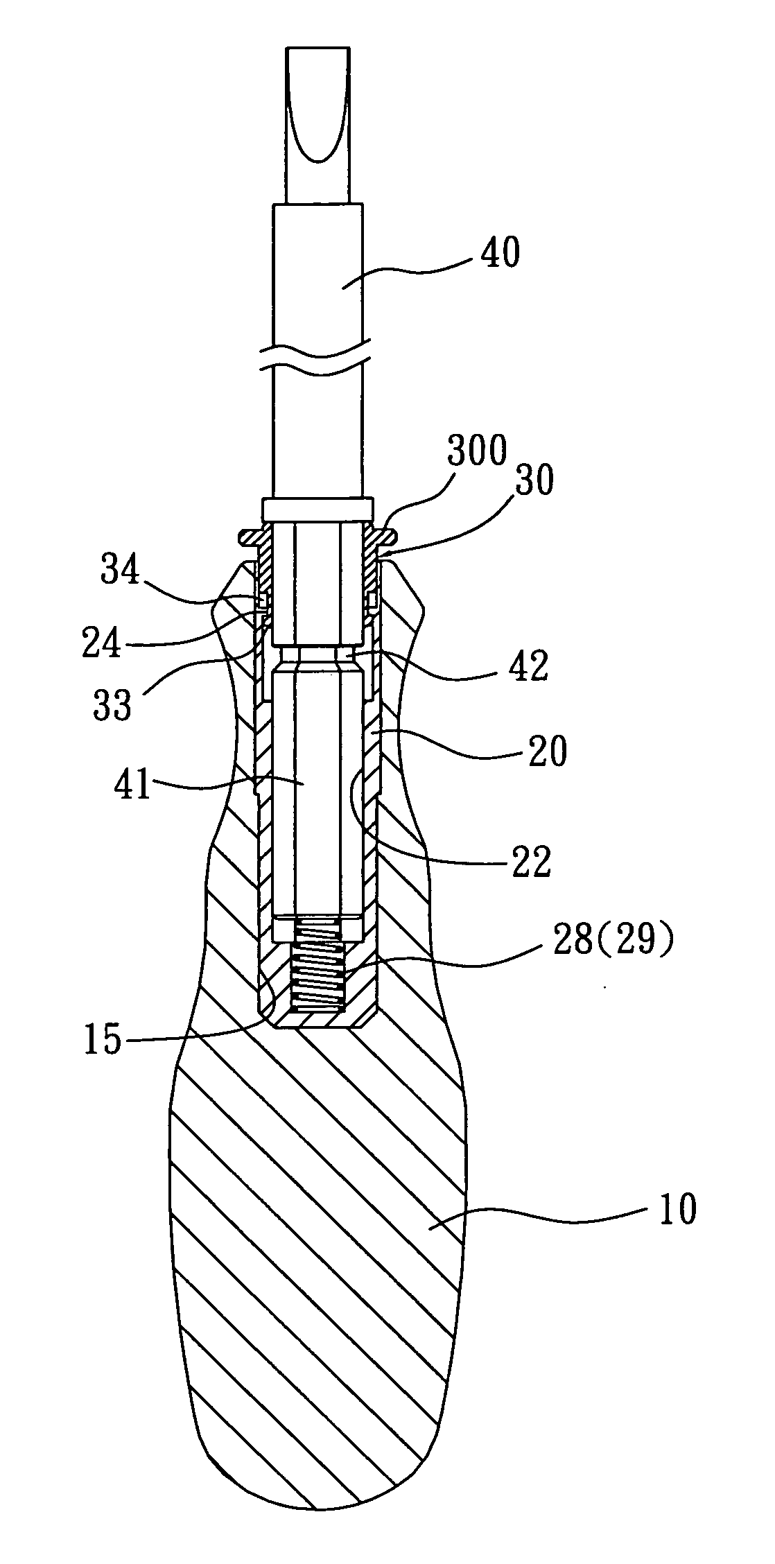
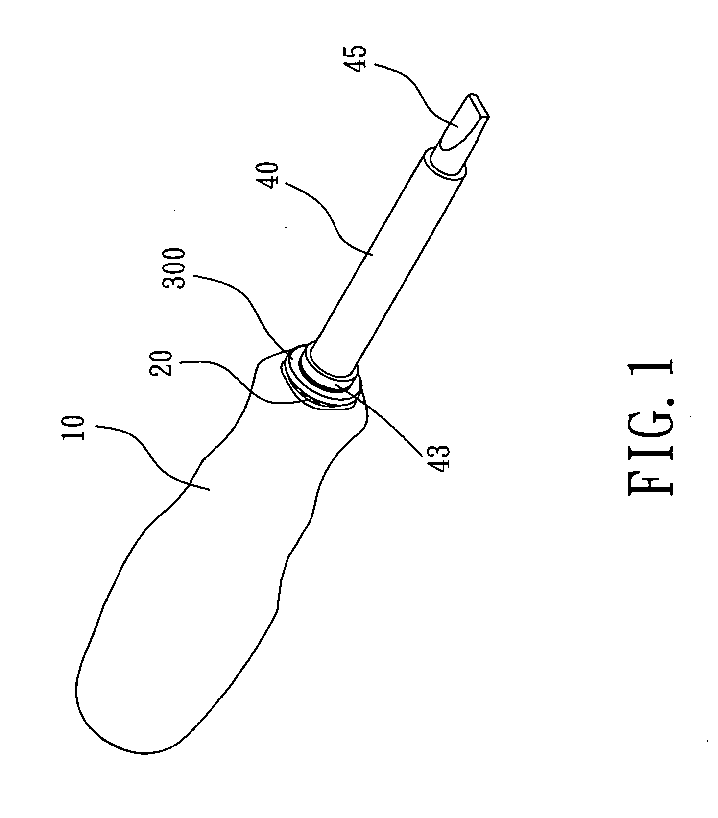
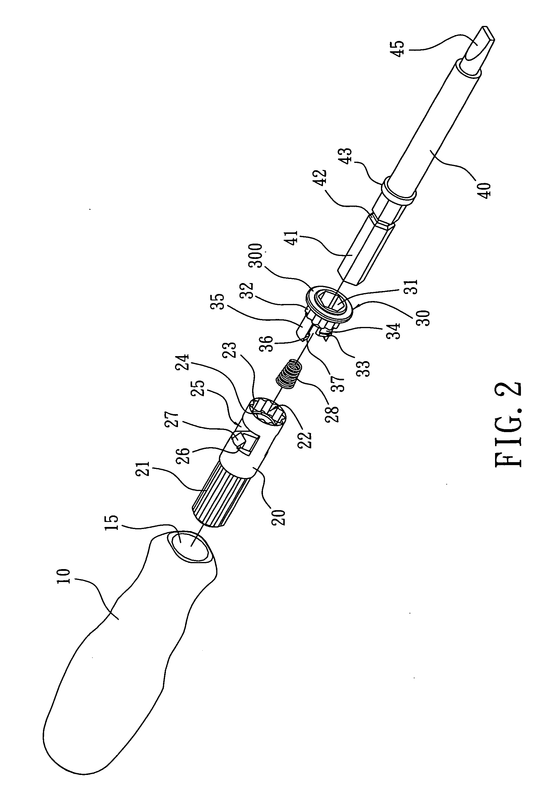
[0018]Referring to the drawings and initially to FIGS. 1-4, a screwdriver in accordance with the preferred embodiment of the present invention comprises a handle 10, a fixing member 20 mounted in the handle 10, a release member 30 slidably mounted on and axially movable relative to the fixing member 20, and a tool shank 40 locked on the release member 30 and detachable from the release member 30 by movement of the release member 30 relative to the fixing member 20.

[0019]The handle 10 has an end portion formed with a receiving slot 15 to allow insertion of the fixing member 20.

[0020]The fixing member 20 is inserted into and fully hidden in the receiving slot 15 of the handle 10. The fixing member 20 has an outer wall formed with a tooth-shaped engaging portion 21 engaged in a wall of the receiving slot 15 of the handle 10 so that the fixing member 20 is secured in and not rotatable relative to the handle 10. The fixing member 20 has an inside formed with an axially extending insertio...


PUM


Abstract

A screwdriver includes a handle, a fixing member mounted in the handle, a release member slidably mounted on and axially movable relative to the fixing member, and a tool shank locked on the release member and detachable from the release member by movement of the release member relative to the fixing member. Thus, the tool shank is supported by the fixing member and the release member which are supported by the handle to enhance the strength of the screwdriver so that the screwdriver is not easily broken or worn out, thereby enhancing the lifetime of the screwdriver. In addition, the tool shank is mounted on and detached from the fixing member and the handle by pressing the release member, thereby facilitating the user mounting and replacing the tool shank.

Description

BACKGROUND OF THE INVENTION[0001]1. Field of the Invention[0002]The present invention relates to a screwdriver, and more particularly to a screwdriver having a quick release tool shank.[0003]2. Description of the Related Art[0004]A conventional screwdriver comprises a handle, and a tool shank secured in the handle and having a front end formed with a polygonal insertion hole to allow insertion of a tip. However, the front end of the tool shank defining the polygonal insertion hole has a wall with a reduced thickness, so that the front end of the tool shank is easily broken or worn out during a long-term utilization, thereby decreasing the lifetime of the screwdriver.SUMMARY OF THE INVENTION[0005]The present invention is to mitigate and / or obviate the disadvantage of the conventional screwdriver.[0006]The primary objective of the present invention is to provide a screwdriver having a quick release tool shank.[0007]Another objective of the present invention is to provide a screwdriver...

Claims


Application Information

Patent Timeline
IPC IPC(8): B25B23/16B25G1/00B25B15/00B25B23/00
CPCB25B15/02B25B23/0035B25G3/18B25G1/085B25B23/0042
Inventor LIN, JACK
Owner YIH CHENG FACTORY
Why Eureka
Try Eureka