Signal compressing signal

a signal and compression technology, applied in the field of signal compression system, can solve the problems of inconvenient mode determining procedure, inability to take into account the spectrum differences of motion-compensated interframe dct signals, and inability to apply the scanning regime of the aforementioned method

Inactive Publication Date: 2008-04-17
SAMSUNG ELECTRONICS CO LTD
View PDF25 Cites 62 Cited by
  • Summary
  • Abstract
  • Description
  • Claims
  • Application Information

AI Technical Summary

Problems solved by technology

However, the scanning regime of the aforementioned method does not take account of differences in the spectrum of the motion-compensated interframe DCT signal with time.
This mode determining procedure is undesirably complicated.

Method used


Image

  • Signal compressing signal
  • Signal compressing signal
  • Signal compressing signal

Examples


Embodiment Construction

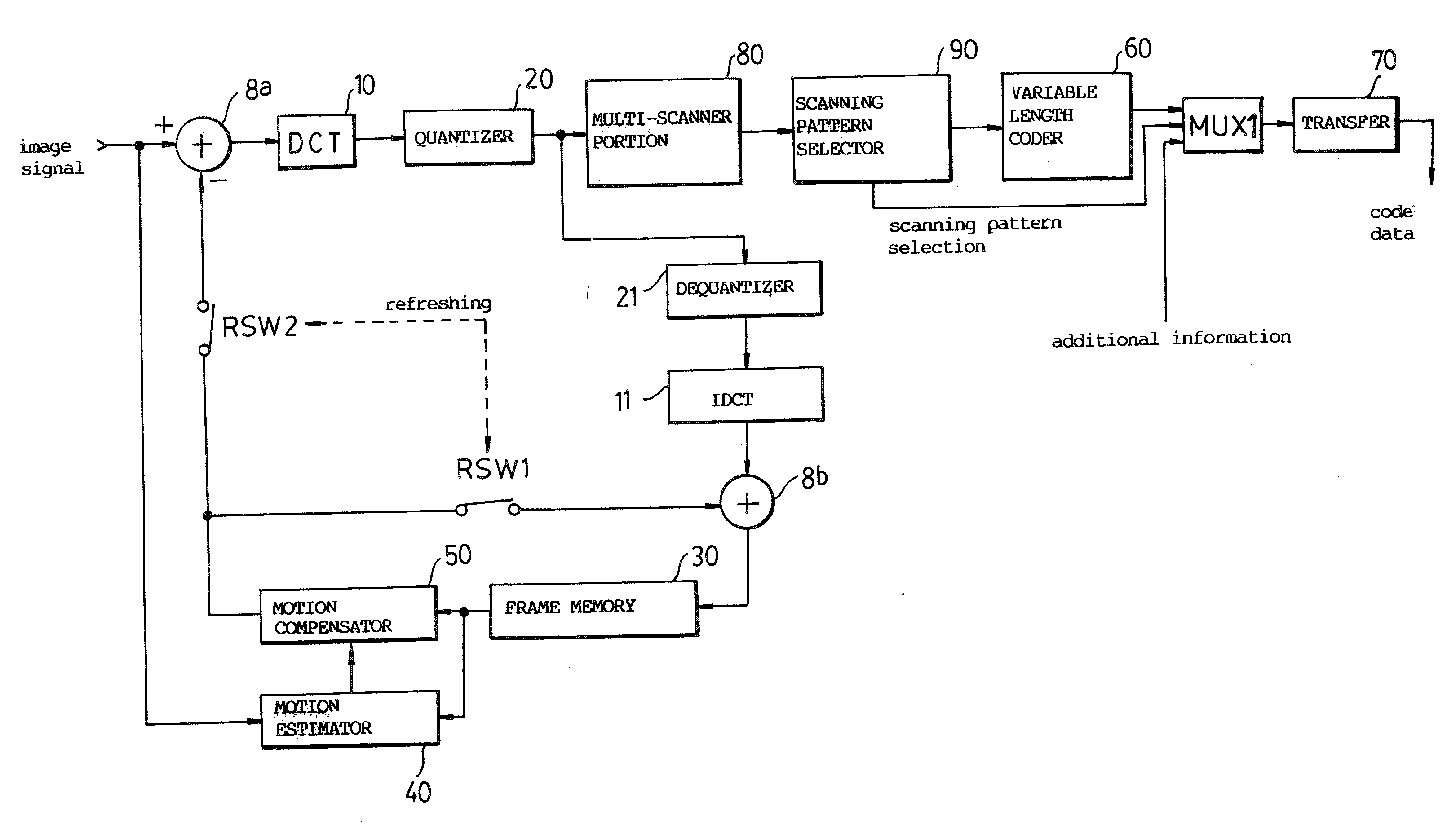
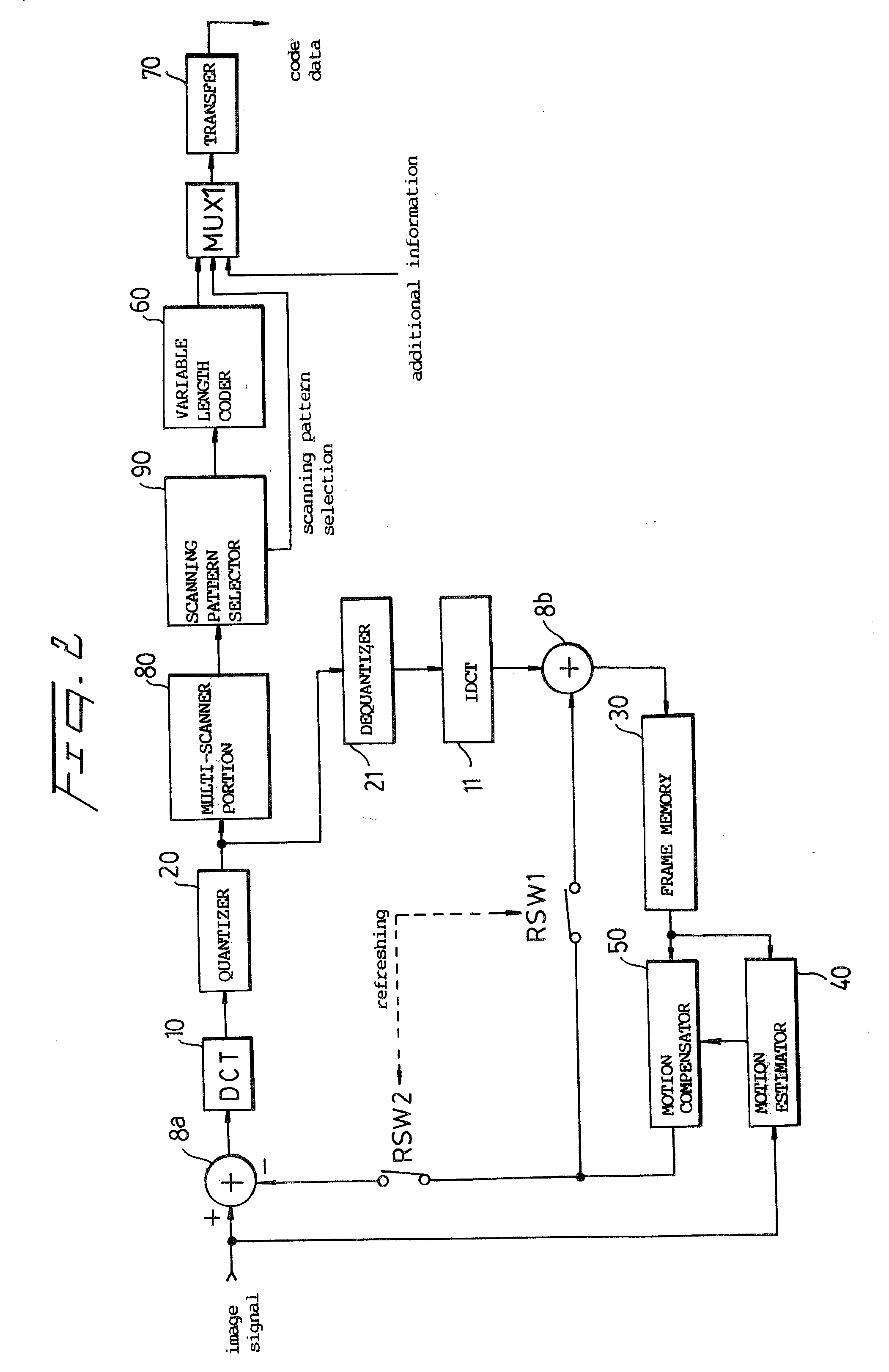
[0022] Referring to FIG. 2, an input signal is divided into equal-sized sub-blocks, for example, 8×8, 16×16, . . . . A motion estimator 40 determines a motion vector by comparing the current frame and a one frame delayed signal from a frame memory 30.

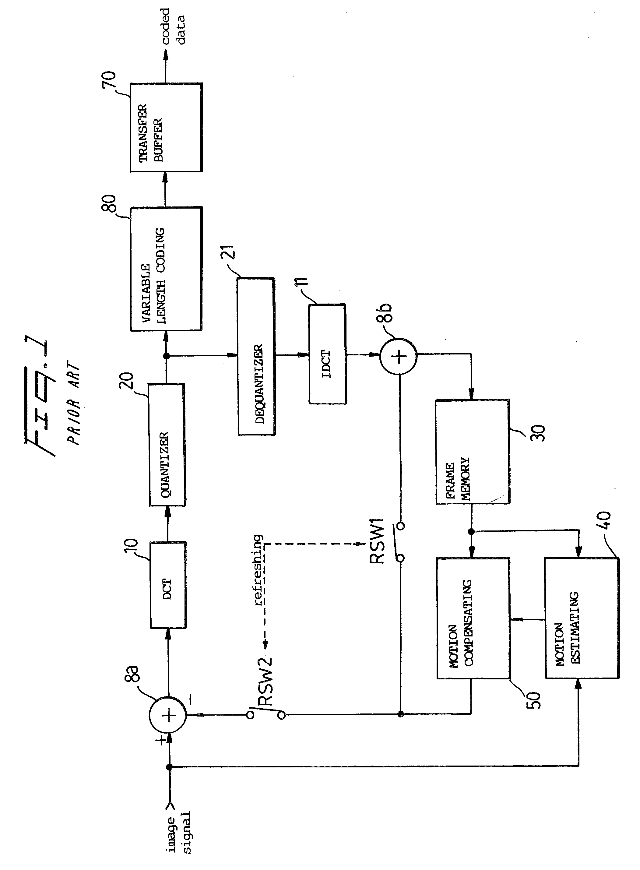
[0023] The motion vector is supplied to a motion compensator 60 which, in turn, compensates the delayed frame signal for movement. A first adder 8a produces a difference signal representing the difference between the present frame and the delayed, motion-compensated frame. A DCT coder 10 DCT-codes the difference signal. The DCT coded image signal is quantized by a quantizer 20 and then dequantized by a dequantizer 21. The dequantized signal is supplied to a second adder 8b, via IDCT 11, which adds it to the output of the motion compensator 11. This produces a signal corresponding to the original image signal.

[0024] The output of the motion compensator 50 is applied to the adders 8a, 8b by refresh switches RSW2 and RSW1, respectively. ...


PUM


Abstract

A multi-scanner scans a signal according to several different patterns. A scanning pattern selector determines which scanning pattern produced the most efficient coding result, for example, for runlength coding, and outputs a coded signal, coded most efficiently, and a selection signal which identifies the scanning pattern found to be most efficient.

Description

CROSS-REFERENCES TO RELATED PATENT APPLICATIONS [0001] This is a Continuation of application Ser. No. 10 / 612,013, filed Jul. 3, 2003; which is a Continuation of application Ser. No. 09 / 703,649, filed Nov. 2, 2000; which is a Continuation of application Ser. No. 08 / 024,305, filed Mar. 1, 1993; the disclosures of which are incorporated herein by reference.FIELD OF THE INVENTION [0002] The present invention relates to a signal compressing system. A system according to the present invention is particularly suited for compressing image signals. The present disclosure is based on the disclosure in Korean Patent Application No. 92-3398 filed Feb. 29, 1992, which disclosure is incorporated herein by reference. BACKGROUND OF THE INVENTION [0003] Image signals may be compressed by motion-compensated interframe discrete cosine transform (DCT) coding such as is defined by a MPEG (Moving Picture Expert Group) international standard. This form of signal compression has attracted much attention in...

Claims


Application Information

Patent Timeline
Patent Type & Authority Applications(United States)
IPC IPC(8): H04N11/02G06T9/00H04N7/26H04N7/30H04N7/50
CPCH04N19/176H04N19/46H04N19/15H04N19/129H04N19/192H04N19/60H04N19/146H04N19/152H04N19/18H04N19/61
Inventor JE-CHANG, JEONGHEN-HEE, MUN
Owner SAMSUNG ELECTRONICS CO LTD
Why Eureka
Try Eureka