
Electro-thermal vest

a technology of electro-thermal elements and vests, applied in the field of electro-thermal vests, can solve the problems of user not being able to separate the outer lining layer from the inner lining layer, the part gets dirty easily, and the electro-thermal element cannot be separated. , to achieve the effect of getting dirty

Inactive Publication Date: 2008-04-24
HANGZHOU ACEPOWER ELECTRONICS
View PDF8 Cites 11 Cited by
  • Summary
  • Abstract
  • Description
  • Claims
  • Application Information

AI Technical Summary

Benefits of technology

[0012]As mentioned above, in the electrothermal vest of the invention, the combining element detachably combines the inner lining layer with the outer lining layer. Thus the user can disassemble the outer lining layer from the inner lining layer, so that the outer lining layer, which gets dirty easier, can be washed or maintained separately.

Problems solved by technology

Because the outer lining layer is usually exposed in the outside environment, this part gets dirty easily.
Thus, the user needs to clean it frequently.
However, the user can not separate the outer lining layer from the inner lining layer and the electro-thermal element, and it is forbidden to wash the electro-thermal element by water.
That is, it is not convenient to clean the electro-thermal garment.
However, the lifetime of the alkaline battery or NiH battery is short, and the battery module has constant outputs, so that the electro-thermal element will generate constant heat and can not provide the temperature adjusting function.
Therefore, the conventional electro-thermal garment can not satisfy user's needs.

Method used


Image

  • Electro-thermal vest
  • Electro-thermal vest
  • Electro-thermal vest

Examples


Embodiment Construction

[0017]The present invention will be apparent from the following detailed description, which proceeds with reference to the accompanying drawings, wherein the same references relate to the same elements.

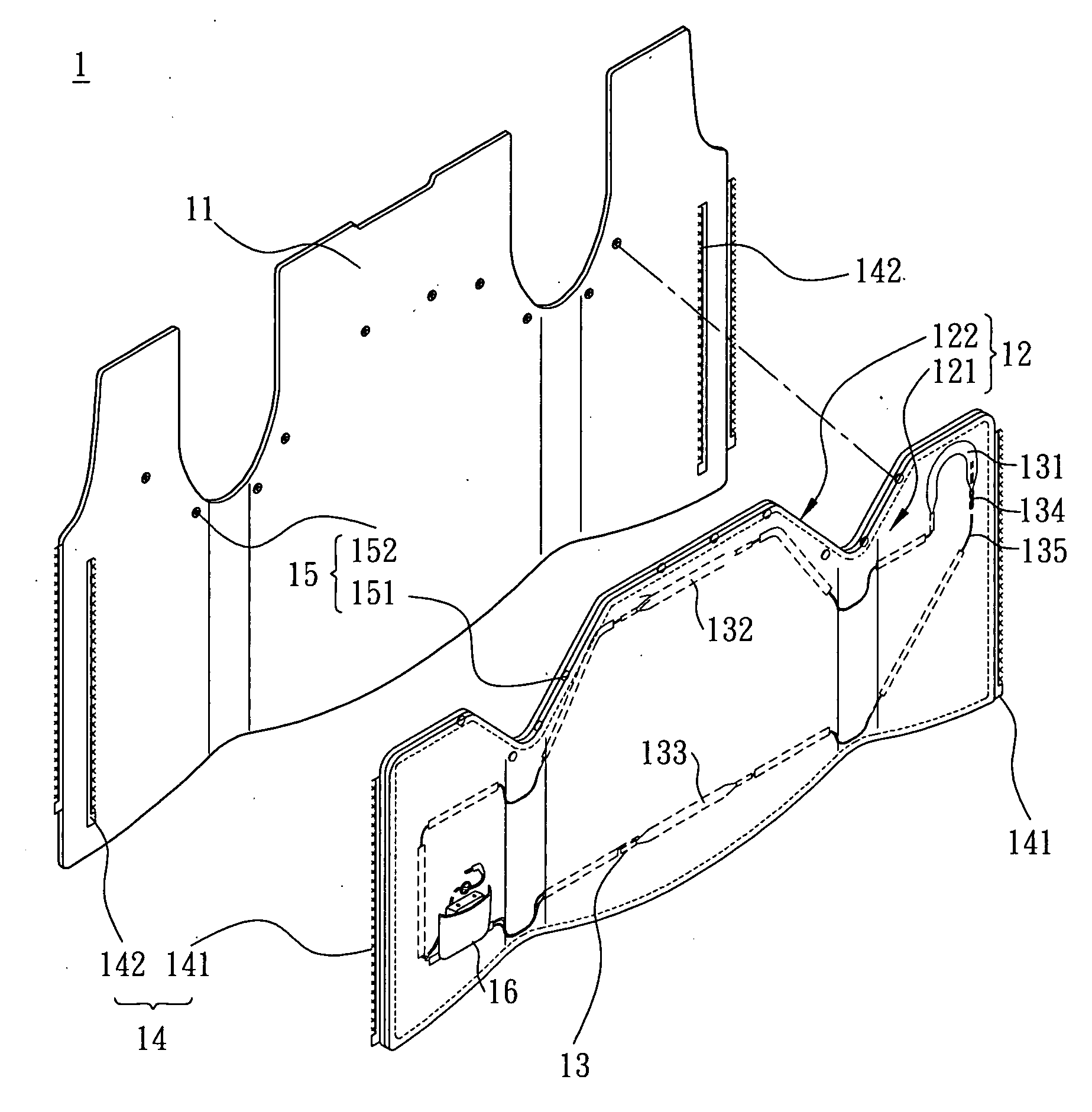
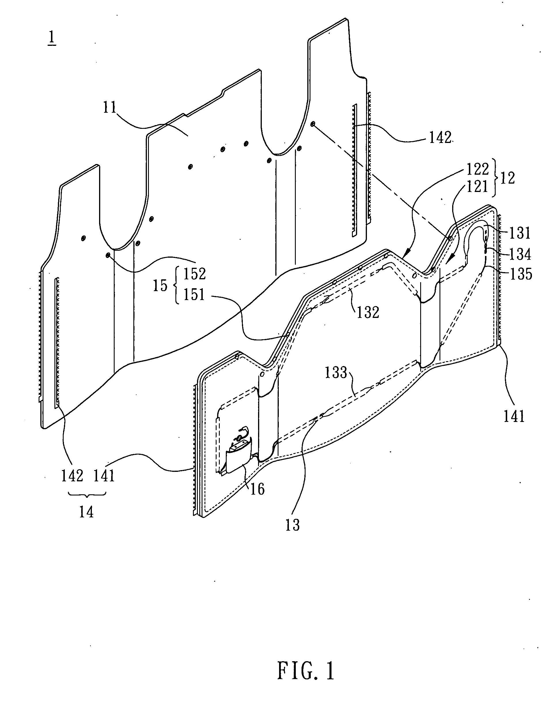
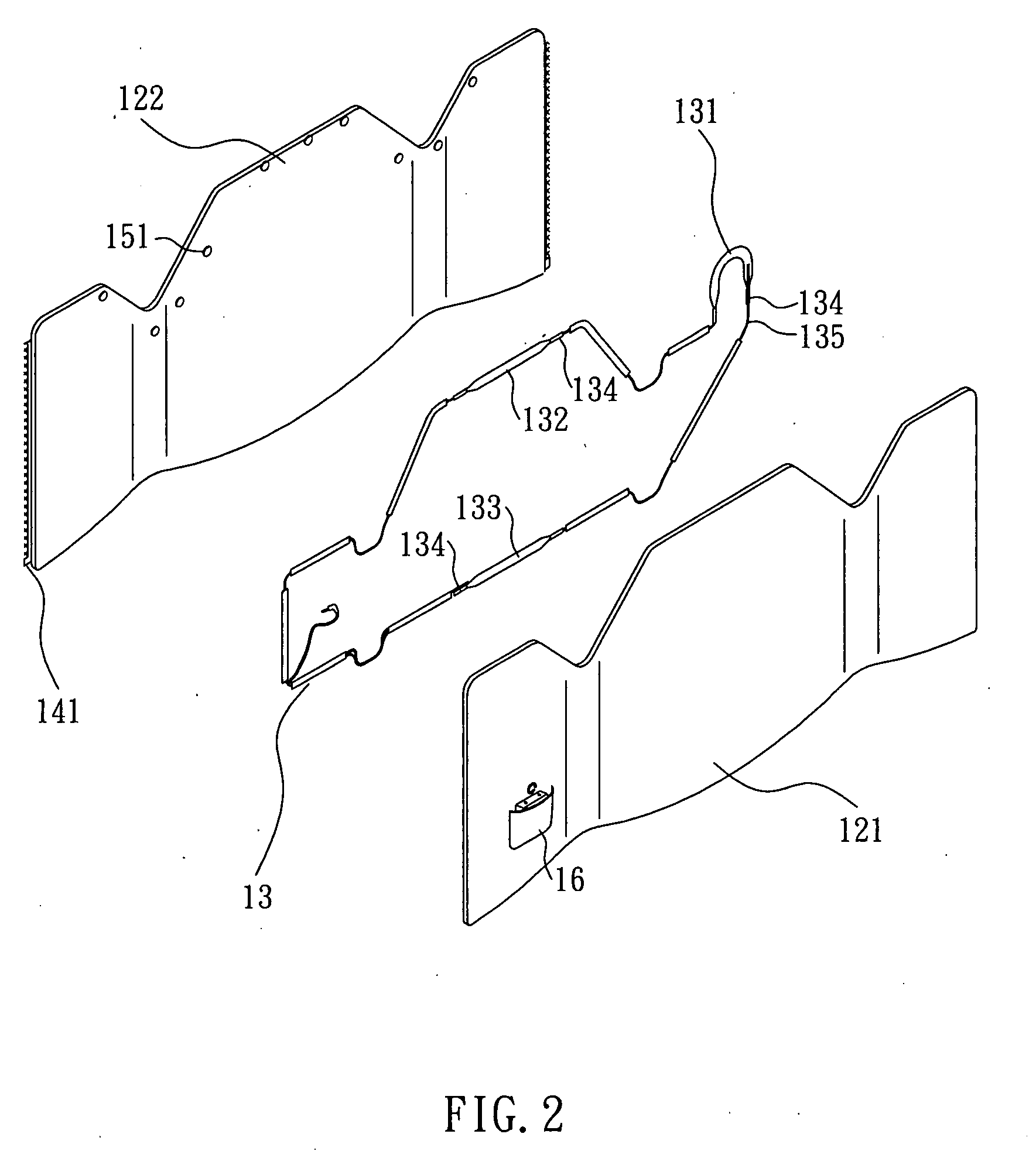
[0018]Referring to FIG. 1 and FIG. 2, an electro-thermal vest 1 according to a preferred embodiment of the invention includes an outer lining layer 11, an inner lining layer 12, an electro-thermal element 13 and a plurality of combining elements 14 and 15. FIG. 1 depicts that the outer lining layer 11 and the inner lining layer 12 are disassembled. FIG. 2 depicts that the inner lining layer 12 and the electro-thermal element 13 are disassembled. The inner lining layer 12 has a first lining 121 and a second lining 122. The electro-thermal element 13 is fixed on the second lining 122 and disposed between the first lining 121 and the second lining 122. The combining elements 14 and 15 detachably combine the inner lining layer 12 with the outer lining layer 11.

[0019]After the inner lining...


PUM


Abstract

An electro-thermal vest of the invention includes an outer lining layer, an inner lining layer, an electro-thermal element and a combining element. The inner lining layer has a first lining and a second lining. The electro-thermal element is fixed on the second lining and disposed between the first lining and the second lining. The combining element detachably combines the inner lining layer with the outer lining layer.

Description

BACKGROUND OF THE INVENTION[0001]1. Field of Invention[0002]The invention relates to a garment, and, in particular, to an electro-thermal garment.[0003]2. Related Art[0004]An electro-thermal garment usually contains an electrothermal element driven by a power source so as to produce heat for defending against the cold.[0005]The conventional electro-thermal garment includes an inner lining layer, an electro-thermal element and an outer lining layer. The inner and outer lining layers are the inside and outside of the electro-thermal garment. The electro-thermal element is sewed on the inner lining layer. The outer lining layer covers the electrothermal element and it is sewed with the inner lining layer. So the electro-thermal element is fixed between the inner and outer lining layers. In this case, the inner lining layer, the outer lining layer and the electro-thermal element are combined together and can not be detached.[0006]Because the outer lining layer is usually exposed in the ...

Claims


Application Information

Patent Timeline
Patent Type & Authority Applications(United States)
IPC IPC(8): H05B1/00
CPCH05B3/342H05B2203/036H05B2203/017A41D13/0051
Inventor FANG, JIMCHEN, KIFFWU, HAIYAN
Owner HANGZHOU ACEPOWER ELECTRONICS
Learn More