Twin Recliner for Automotive Seats

a recliner and seat technology, applied in the field of auto seats, can solve the problems of single recliner not being able to withstand the subjected load, the guide walls of the pawls or the inner sector may wear out, and the recliner may not be able to meet the load, so as to facilitate the disengagement and/or engagement of the mating parts

Inactive Publication Date: 2008-04-24
IFB AUTOMOTIVE PTE LTD
View PDF8 Cites 20 Cited by
  • Summary
  • Abstract
  • Description
  • Claims
  • Application Information

AI Technical Summary

Benefits of technology

[0011]The present invention provides a twin recliner for a seat, which permits the reclining of the seat back with respect to the seat cushion. The recliner, which includes master (door side) and slave recliner assemblies and individual components or the sub-assemblies for the slave and the master (door side) recliners, are mirror image parts. The master and the slave recliner assemblies are at the transition of seat back and the seat cushion at each side of the seat. Only the master recliner has an actuating hand lever operating directly the rotatable cam, and a connecting rod connected to the master recliner transmits the motion to the slave recliner and facilitates the disengagement and / or engagement of the mating parts.

Problems solved by technology

Sometimes, this may result in uneven forces acting on the cam and hence operational difficulties arise as well as increasing the operating effort.
The guide walls that guide the pawls or the inner sectors may wear out due to irregular shape and manufacturing process.
The necessity of twin recliner becomes significant when the seat size is increased such that a single recliner fails to endure the subjected loads.
The constraints that limit the functioning of the twin recliner assembly include failure of recliners to operate simultaneously due to loss in transmission, very high operating forces, teeth breakage because of shock forces, slippage due to undershooting and overshooting, endurance failure, so on and so forth.

Method used


Image

  • Twin Recliner for Automotive Seats
  • Twin Recliner for Automotive Seats
  • Twin Recliner for Automotive Seats

Examples


Embodiment Construction

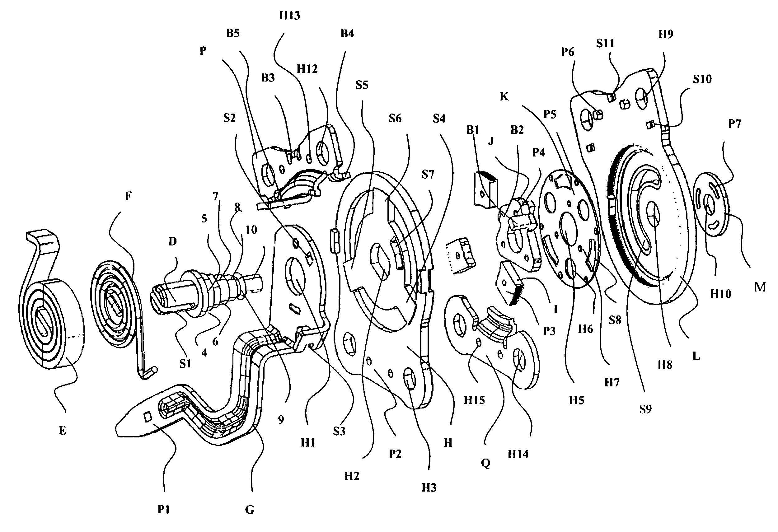
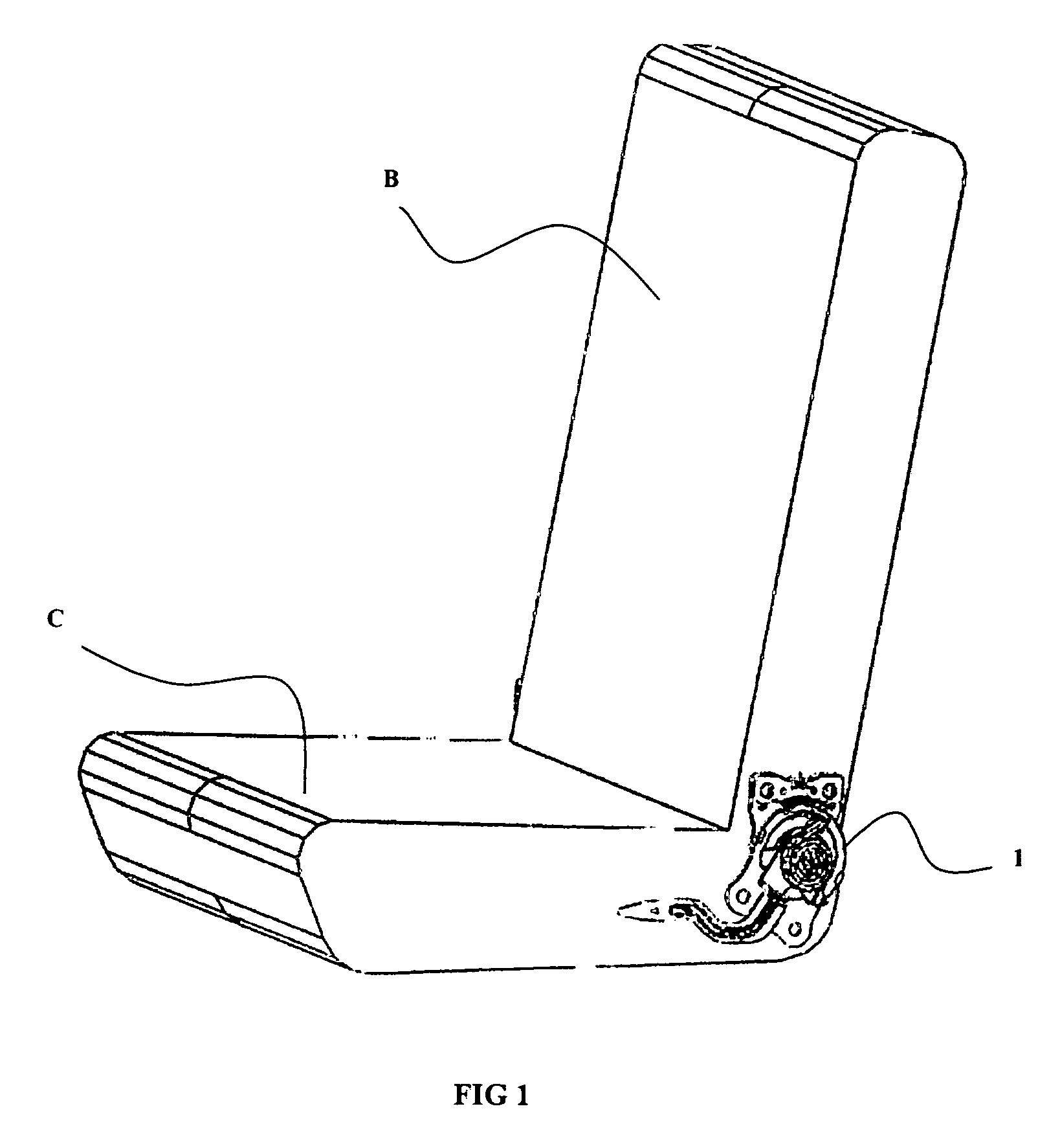
[0020]Referring initially to FIGS. 1-5, an embodiment wherein a twin recliner for automotive seat assembly, according to one embodiment includes a master 1 and a slave recliner 2 suitably connected by means of a connecting rod R (not shown in FIG. 3) are secured to either side ends of the seat assembly. The master recliner having a lower housing H (not mentioned)is mounted onto the seat cushion assembly C, an upper housing L (not mentioned) is mounted onto the seat back assembly, which forms the moving member of the recliner to transmit motion about a hinge on the lower housing H. The lower housing H (not shown) and upper housing L are disposed in an overlapping manner.

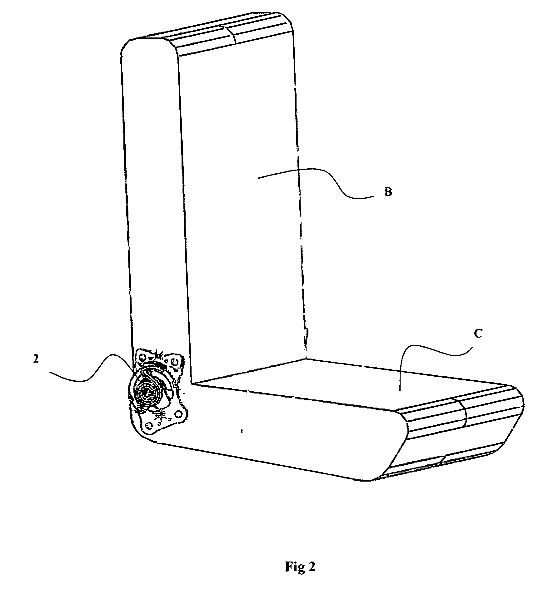
[0021]Now referring to FIG. 3, another embodiment wherein the master recliner 1 is connected to the slave recliner 2 by means of a rotatable connecting rod R (Not shown), having a bracket N, (the connecting bracket on the master side is not shown in this figure) which also has a corresponding rotary movement. The conn...


PUM


Abstract

The present invention provides a twin recliner operable manually for permitting selective position of a seat back with respect to the seat cushion through a range of reclined positions to a selected use position. Said twin recliner comprising: a master and a slave recliner, a shaft arm member with a longitudinal cleavage on one side and a plurality of peripheral stepping arrangement on the other side, an external spring means with one end hooked to the lower portion of the activating lever and the other end locked to the longitudinal cleavage of the shaft to facilitate a nominal return rate of the actuating lever, a rotatable cam mounted on the third of said plurality of stepping arrangement having a projection is engaged with the slot of the lower housing to receive a rotary drive directly from the actuating lever to disengage inner sectors, a guiding plate with a central passage mounted on the fourth of the stepping arrangement of the shaft member to provide a synchronized movement of the inner sectors.

Description

TECHNICAL FIELD[0001]The present invention is in field of automotive seat recliners. The present invention particularly relates to a twin recliner operable manually for permitting selective position of a seat back with respect to the seat cushion through a range of reclined positions to a selected use position.DESCRIPTION OF THE BACKGROUND ART[0002]All vehicles are now equipped with seats having a recliner mechanism that can be selectively actuated for permitting the angular position of the seat back to be varied with respect to the seat cushion.[0003]Generally, seat reclining mechanism includes a lower and upper arm mounted on the seat cushion and seat back respectively, to house a locking cum unlocking means, which is effected by a rotatable cam operated by a splined shaft which passes through the lower and upper arms of the recliner. Spiral springs that are mounted on the shaft, are disposed between the two arms of the recliner to apply radial forces on the cam for rotation durin...

Claims


Application Information

Patent Timeline
Patent Type & Authority Applications(United States)
IPC IPC(8): B60N2/235
CPCB60N2/2356B60N2/236B60N2/235B60N2/22B60N2/02
Inventor NAG, BIJONREDDY, MANYAM HEMADRIRAMALINGAM, MUTHUSAMYRAJAGOPAL, KESAVAN
Owner IFB AUTOMOTIVE PTE LTD
Why Eureka
Try Eureka