Female terminal fitting

a terminal fitting and female technology, applied in the direction of coupling contact members, coupling device connections, coupling/insulating coupling contact members, etc., can solve the problem that the shake preventing portion cannot suppress the shake movement of the male tabs in sufficient degr

Inactive Publication Date: 2008-04-24
SUMITOMO WIRING SYST LTD
View PDF2 Cites 9 Cited by
  • Summary
  • Abstract
  • Description
  • Claims
  • Application Information

AI Technical Summary

Benefits of technology

[0007]The invention relates to a female terminal fitting with opposite front and rear ends. A tube is formed adjacent the front end and has a tab insertion opening at the front end for receiving a male tab. A contact piece is arranged at least partly in the tubular portion and cooperates with a receiving pad in the tube sandwich the male tab together. The contact piece includes a resiliently deformable contact m...

Problems solved by technology

There is a possibility that shaking movements of the male tab will not be suppressed sufficiently by t...

Method used


Image

  • Female terminal fitting
  • Female terminal fitting
  • Female terminal fitting

Examples


Embodiment Construction

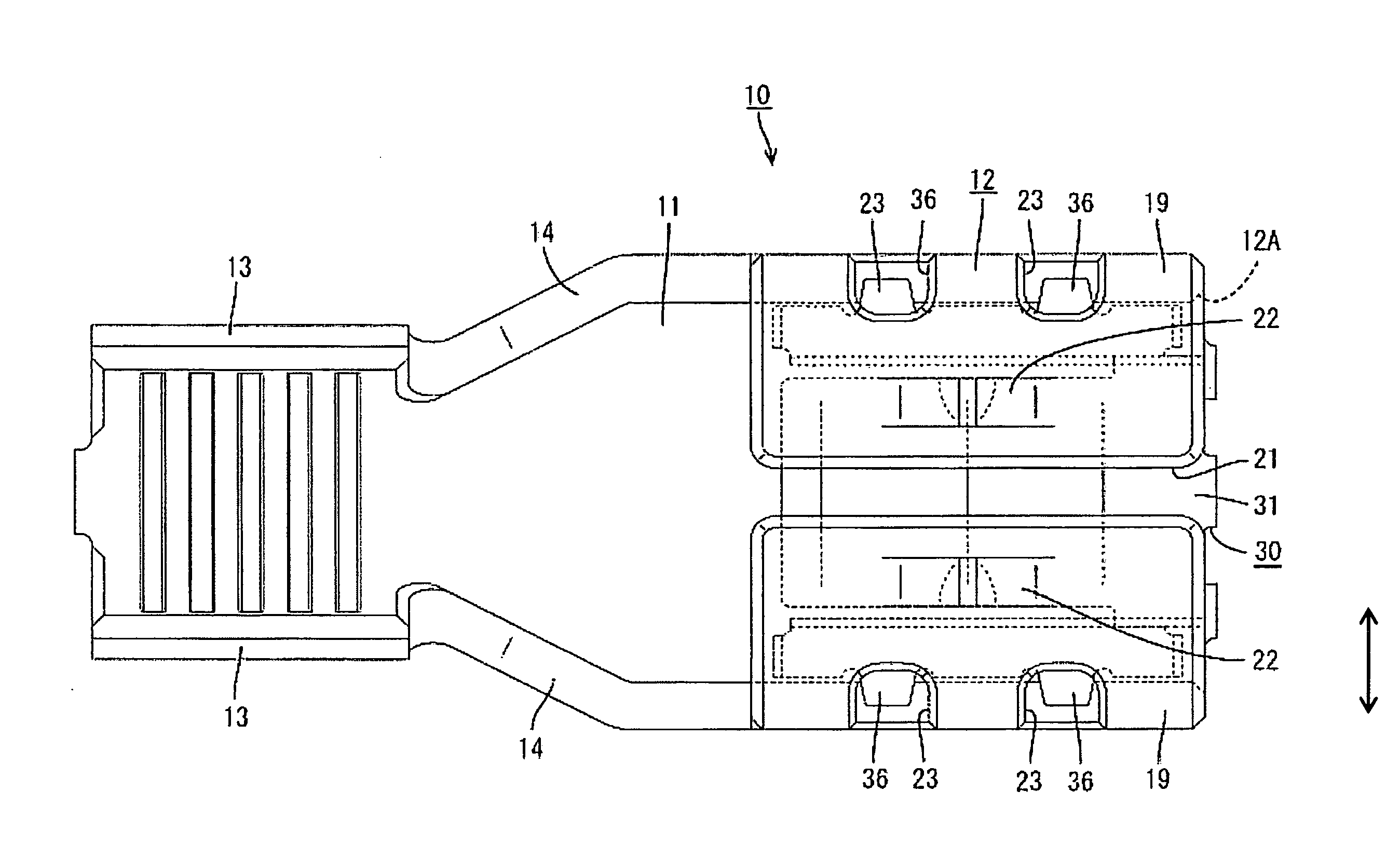
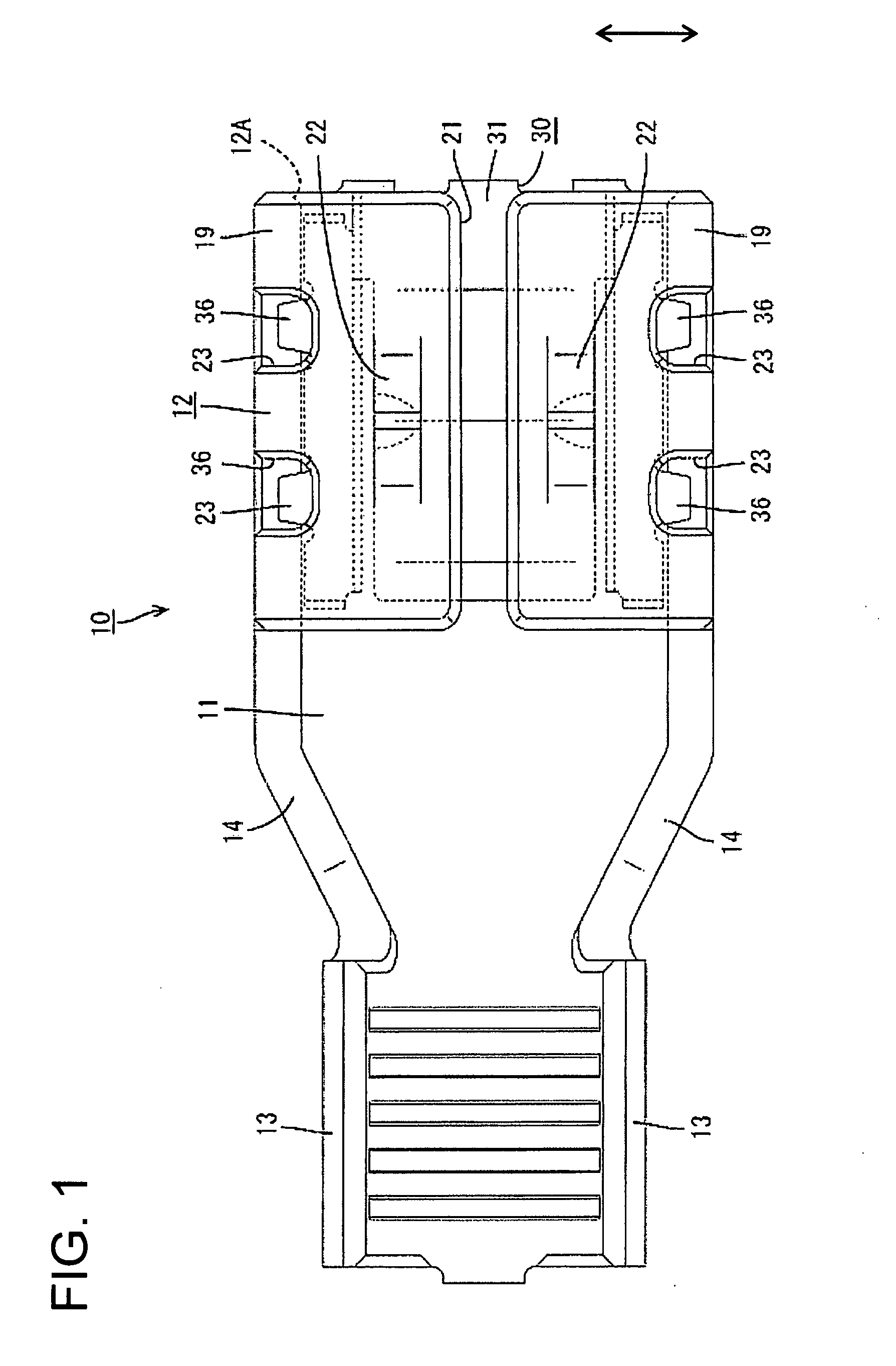
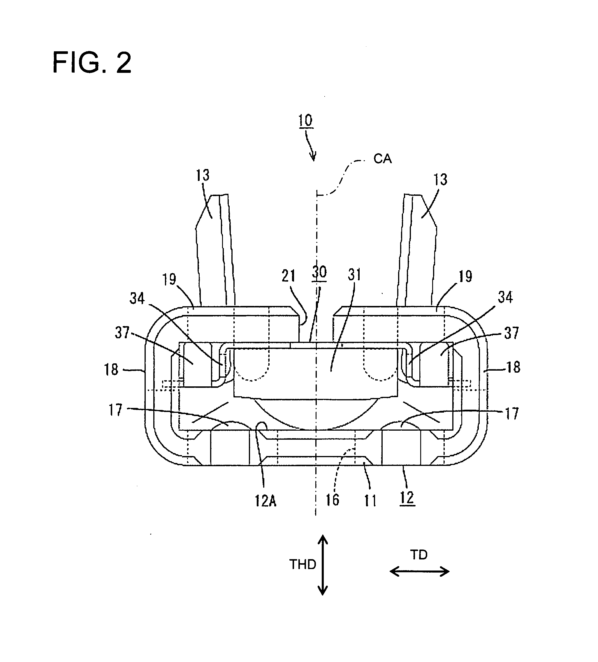
[0027]A female terminal fitting in accordance with the invention is identified generally by the numeral 10 in FIGS. 1 to 9. The female terminal fitting 10 is connectable with a male tab 80, and can be accommodated in an unillustrated connector housing while being connected with an end of a wire. In the following description, a left side in FIG. 3 is a front end concerning forward and backward directions FBD and reference is made to FIG. 2 concerning the vertical direction.

[0028]The female terminal fitting 10 is made of an electrically conductive plate made preferably of metal. In order to cope with an unillustrated thick wire for large current, a relatively thick plate material is used. This female terminal fitting 10 includes a substantially flat base plate 11 that extends in forward and backward directions FBD. A substantially rectangular tube 12 is formed along a front part of the base plate 11 and a wire connection barrel 13 is formed along a rear part of the base plate 11. The ...


PUM


Abstract

A female terminal fitting (10) has a tube (12) with a tab insertion opening (12A) for receiving a male tab (80). A contact piece (30) and receiving pads (17) are provided in the tube (12) for sandwiching the male tab (80). The contact piece (30) includes a resiliently deformable contact main body (31) that is curved to come closer to the receiving pads (17) and can resiliently contact a widthwise middle part of a plate surface of the male tab (80) at a convex contact position along the curve. Shake preventing portions (32) are formed at opposite sides of the contact main body (31) and contact opposite sides of the male tab (80) for preventing the male tab (80) from shaking about the center of axis thereof.

Description

BACKGROUND OF THE INVENTION[0001]1. Field of the Invention[0002]The invention relates to a female terminal fitting.[0003]2. Description of the Related Art[0004]Japanese Unexamined Patent Publication No. 2006-12741 discloses a long narrow female terminal fitting with opposite front and rear ends. A tube is formed at the front end of the female terminal fitting and is dimensioned to receive a mating male tab. A barrel is formed at the rear end and is configured to be connected with an end of a wire. A contact piece in the form of a leaf spring is formed separate from the tube, but is inserted in the tube. The contact piece has a main body that is curved in a substantially U-shape. The main body has contact portion with a convex surface disposed for contacting a male tab. The male tab inserted into the tube is connected electrically with the female terminal fitting while being resiliently sandwiched between the contact portion of the contact piece and a receiving pad in the tube. The c...

Claims


Application Information

Patent Timeline
IPC IPC(8): H01R13/11
CPCH01R13/113H01R13/187H01R13/11
Inventor FUKAYA, TOMOYOSHITANAKA, TSUTOMU
Owner SUMITOMO WIRING SYST LTD
Why Eureka
Try Eureka