Catheter having markers to indicate rotational orientation

a technology of rotating orientation and catheters, applied in the field of radiopaque markers, can solve the problems that the components at the working end of the catheter (e.g., balloons, ports, etc., may be difficult to identify using fluoroscopy

Inactive Publication Date: 2008-04-24
ABBOTT LAB INC
View PDF6 Cites 68 Cited by
  • Summary
  • Abstract
  • Description
  • Claims
  • Application Information

AI Technical Summary

Benefits of technology

[0004]To achieve the foregoing and other objects of the invention, various improved catheter marking arrangements are described. In a first aspect of the invention, a first longitudinally extending radiopaque marker is positioned on the catheter. A second longitudinally extending radiopaque marker is positioned opposite the first marker at a rotational orientation that is approximately 180 degrees offset from the first marker. The second marker has a length that is sufficiently different from the first marker such that a surgeon utilizing the catheter in a surgical procedure would be able to readily differentiate the first and second markers in a fluoroscopic image based on their respective lengths (or other features) in order to determine the rotational orientation of the catheter.

Problems solved by technology

Often, some of the components at the working end of the catheter (e.g., balloons, ports, etc.) may be difficult to identify using fluoroscopy in the midst of a surgical procedure.

Method used


Image

  • Catheter having markers to indicate rotational orientation
  • Catheter having markers to indicate rotational orientation
  • Catheter having markers to indicate rotational orientation

Examples


Embodiment Construction

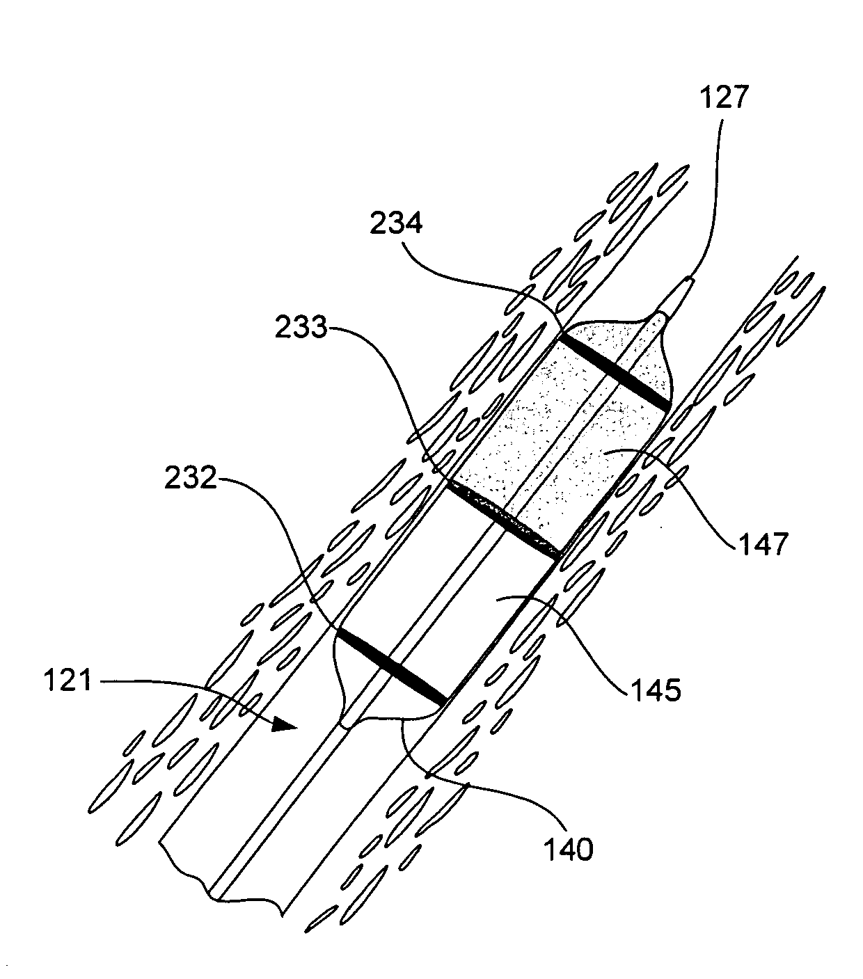
[0014]The present invention relates generally to specific marker configurations that are suited for use with specific types of catheters.

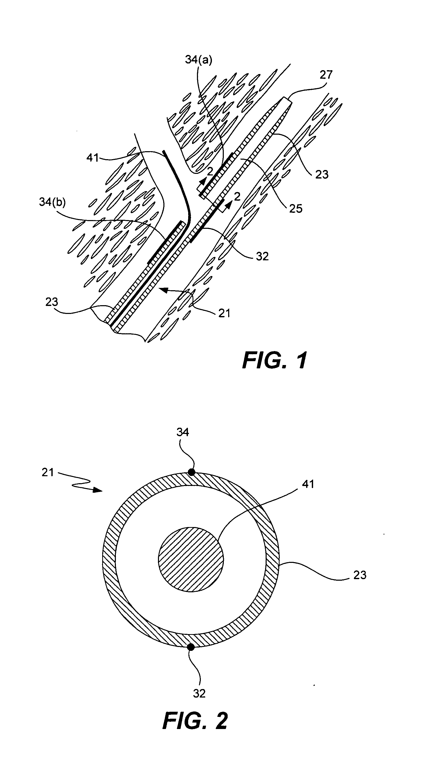
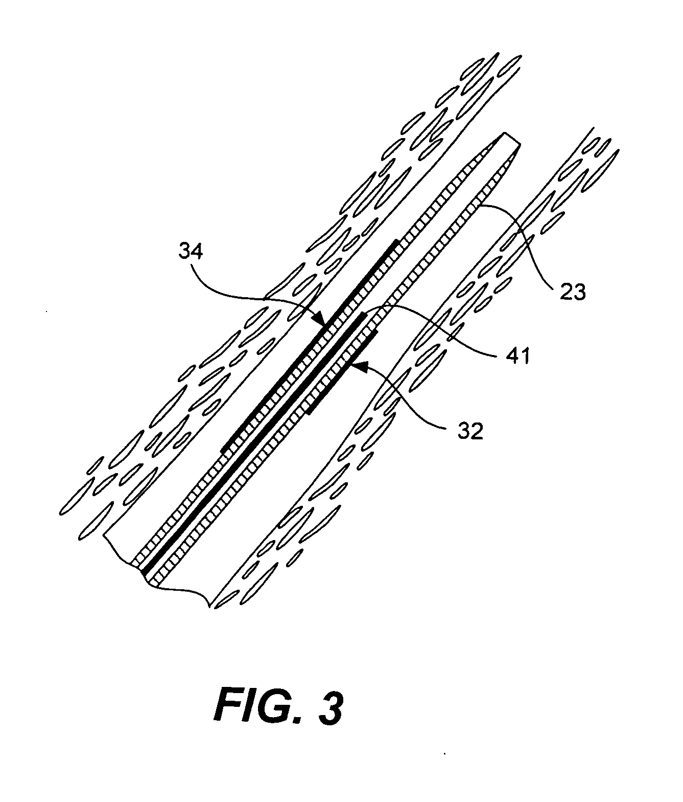
[0015]Referring initially to FIG. 1, a marker arrangement arranged to mark the rotational orientation of the distal end of a catheter in accordance with one embodiment of the invention will be described. The catheter 21 is generally formed from an elongated tubular member 23 having central lumen 25 formed therein. The central lumen opens at the distal end of the catheter at a distal port 27 such that the catheter can be inserted into a target vessel over a guide wire 41. The catheter also has a side port 29 that opens to the side of the catheter. This type of side port can be useful in a variety of different catheter designs, as for example in certain bifurcation catheters, atherectomy catheters, perfusion catheters, and support catheter designs.

[0016]A first longitudinally extending marker 32 is positioned on the side of the catheter opposite the ...


PUM


Abstract

Various improved catheter marking arrangements are described. In a first aspect of the invention, a first longitudinally extending radiopaque marker is positioned on the catheter. A second longitudinally extending radiopaque marker is positioned opposite the first marker at a rotational orientation that is approximately 180 degrees offset from the first marker. The second marker has a length that is sufficiently different from the first marker such that a surgeon utilizing the catheter in a surgical procedure would be able to readily differentiate the first and second markers in a fluoroscopic image based on their respective lengths in order to determine the rotational orientation of the catheter.
In some embodiments, the catheter includes a lumen that has a side port that opens to a side of the catheter. The first marker is composed of a pair of axially aligned marker segments located on opposite ends of the side port. The length of the first longitudinal extending marker defined as an end-to-end length of the pair of axially aligned marker segments is longer than the length of the second marker. The markers may be formed from any suitable materials that can be clearly detected by an imaging system.

Description

BACKGROUND OF THE INVENTION[0001]The present invention relates generally to radiopaque markers provided on catheters to help surgeons position and / or orient specific components of the catheters during use.[0002]Catheters are used in a wide variety of medical procedures. Typically catheters are relatively long and flexible. Many times, (as for example in many vascular applications) a catheter is inserted into a relatively tortuous vessel. In order to better track the location of the catheter, it is common to image the catheter during its insertion, placement and / or use. Thus, the surgeon can see that the catheter is properly positioned in situ. Today, one of the most common surgical imaging techniques is fluoroscopy. Often, some of the components at the working end of the catheter (e.g., balloons, ports, etc.) may be difficult to identify using fluoroscopy in the midst of a surgical procedure. Accordingly, radiopaque markers have sometimes been used to mark specific points on a cathe...

Claims


Application Information

Patent Timeline
Patent Type & Authority Applications(United States)
IPC IPC(8): A61M25/098A61M29/00A61F2/06A61F2/00
CPCA61F2/856A61F2/954A61F2/958A61M2025/1079A61M25/0108A61M2025/0008A61F2250/0098
Inventor YRIBARREN, TRAVIS R.OEPEN, RANDOLF VONCOFFEY, LORCANRIETH, THOMASZUCKER, ARIK
Owner ABBOTT LAB INC
Why Eureka
Try Eureka