Driving force control apparatus

Inactive Publication Date: 2008-04-24
TOYOTA JIDOSHA KK
View PDF1 Cites 21 Cited by
  • Summary
  • Abstract
  • Description
  • Claims
  • Application Information

AI Technical Summary

Benefits of technology

[0014] Preferably, the output control unit brings the cancel switch into an off state if a predetermined drive condition is met. This configuration can reliably prevent the driver from forgetting to return the cancel switch (or from forgetting to turn off the switch).
[0015] The driving force control apparatus according to the present invention is preferably configured as follows: it further comprises a grade detecting unit for detecting a grade of a driving road, and the output control unit raises an output restraint value of the power plant according to a magnitude of an up grade of the driving road. This configuration makes it feasible to output a required drive torque, for example, at a start on an upgrade or the like.
[0016] The driving force control apparatus according to the present invention is preferably configured as follows: it further comprises a grade detecting unit for detecting a grade of a driving road, and the output control

Problems solved by technology

It is, however, difficult to zero erroneous detection of the obstacle in real complex circumstances (traffic circumstances and natural environments) where the vehicle is located.
Therefore, it is also difficult to perfectly zero erroneous detection in detection of the stepping error on the accelerator pedal from the detection result of the obstacle and the position of the accelerator pedal.
If erroneous d

Method used


Image

  • Driving force control apparatus
  • Driving force control apparatus
  • Driving force control apparatus

Examples


first embodiment

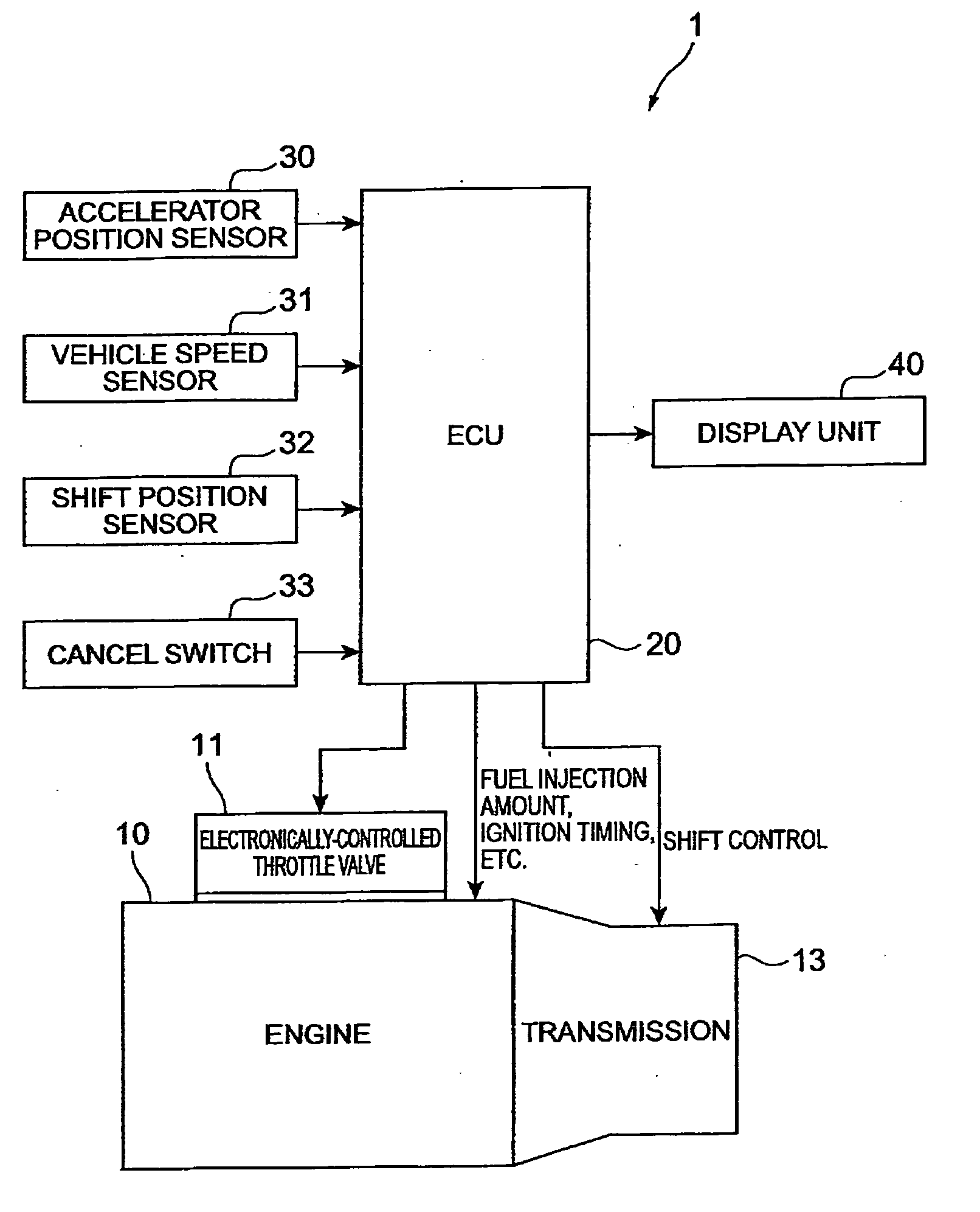
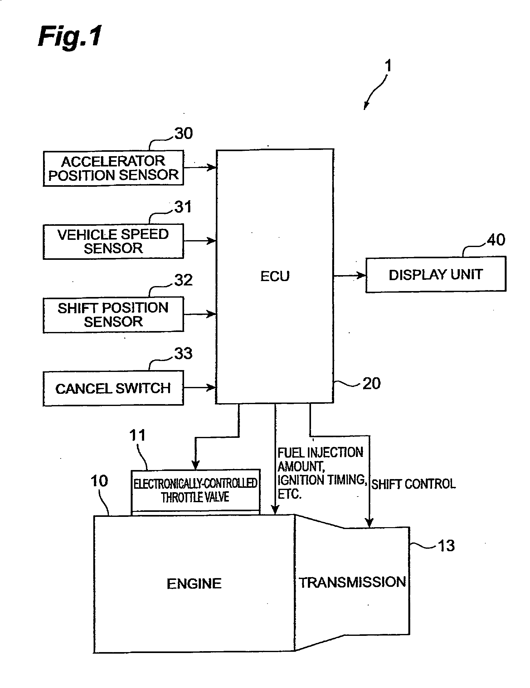
[0024] First, a configuration of driving force control apparatus 1 according to the first embodiment will be described using FIG. 1. FIG. 1 is a block diagram showing the configuration of the driving force control apparatus 1.

[0025] The driving force control apparatus 1 is arranged to restrain an output of engine 10 being a power plant for generating a driving force to drive a vehicle, from increasing over a predetermined value, in a region where a position of an accelerator pedal is not less than a predetermined value, and to relax the restraint on the output of the engine 10 if a predetermined output restraint relaxation condition is satisfied, whereby the apparatus suppresses a sudden change of vehicle behavior against driver's intention, e.g., sudden starting, sudden acceleration, and so on, caused by a stepping error on the accelerator pedal, while preventing the driver from feeling strong inconsistency.

[0026] In the present embodiment, the engine 10 used is a gasoline engine...

second embodiment

[0052] Next, a configuration of driving force control apparatus 2 according to the second embodiment will be described using FIG. 4.

[0053]FIG. 4 is a block diagram showing the configuration of the driving force control apparatus 2. In FIG. 2 identical or equivalent components to those in the first embodiment are denoted by the same reference symbols.

[0054] The driving force control apparatus 2 is different from the aforementioned first embodiment in that it is provided with a road grade sensor 34 for detecting a grade (up grade or down grade) of a driving road at a stop or during low-speed steady driving and provided with an ECU 20A for restraining the output of engine 10 also taking the road grade into consideration, instead of the ECU 20. The road grade sensor suitably applicable is an acceleration sensor or the like. The other configurations are the same as or similar to those in the aforementioned first embodiment, and thus the description thereof is omitted herein.

[0055] The...


PUM


Abstract

A driving force control apparatus has an electronically-controlled throttle valve for regulating an intake air mass of an engine, and an ECU for controlling this electronically-controlled throttle valve. The ECU keeps an opening of the electronically-controlled throttle valve constant to restrain increase of engine output, in a region where a position of an accelerator pedal (accelerator travel) is not less than a predetermined travel AC1. The ECU relaxes the restraint on the output of the engine when a predetermined output restraint relaxation condition is satisfied, e.g., when a speed of a vehicle becomes higher than a predetermined speed (e.g., 20 km/h), or when the shift position is a predetermined position (e.g., D1 (first gear fixed), or D2 (second gear fixed) position).

Description

BACKGROUND OF THE INVENTION [0001] 1. Field of the Invention [0002] The present invention relates to driving force control apparatus and, more particularly, to a driving force control apparatus for suppressing a sudden change of vehicle behavior caused by a stepping error on an accelerator pedal. [0003] 2. Related Background Art [0004] There is the conventionally proposed technology of detecting a stepping error on the accelerator pedal instead of the brake pedal and suppressing a sudden vehicle behavior change against driver's intention such as a sudden start or sudden acceleration occurring as a result of the stepping error (e.g., Patent Document 1: Japanese Patent Application Laid-open No. 05-256170). [0005] Patent Document 1 discloses the following technology: when the driver steps largely on the accelerator pedal in a situation in which an obstacle is detected in front of the vehicle from the detection result of a laser sensor, the throttle valve is forcibly closed, while judgi...

Claims


Application Information

Patent Timeline
IPC IPC(8): G06F17/00
CPCF02D11/105F02D11/107F02D2200/602F02D2200/501F02D41/0225
Inventor KAWAKAMI, SEIJI
Owner TOYOTA JIDOSHA KK
Why Eureka
Try Eureka