Extremity armor

a technology of extreme armor and body armor, applied in the direction of protective equipment, weapons, protective garments, etc., can solve the problems of not offering complete arm and leg protection, not designed for comfort factors such as heat, long-time wear, mobility, flexibility,

Inactive Publication Date: 2008-05-01
USA AS REPRESENTED BY THE SEC OF THE NAVY THE +3
View PDF4 Cites 27 Cited by
  • Summary
  • Abstract
  • Description
  • Claims
  • Application Information

AI Technical Summary

Benefits of technology

[0097]Thus, the present invention is well adapted to carry out the objects and attain the ends and advantages mentioned above as well as those inherent therein. While presently preferred embodiments have been described for purposes of this disclosure, numerous changes and modifications will be apparent to those in the art. Such changes and modifications are encompassed within this invention as defined by the appended claims.

Problems solved by technology

However, due to the closer proximity to the blast, the arms and legs are vulnerable.
None of these options offers complete arm and leg protection.
As a result, they are not designed for comfort factors like heat, long-time wear, mobility, flexibility, and the like.
Moreover, the threat to the soldier is 360 degrees, as opposed to merely the frontal assault, so the SWAT team options leave the rear vulnerable.
This equipment has a very high degree of frontal protection but is very heavy, hot and cumbersome, and not suitable for the foot soldier.
There is no suitable product available for foot soldiers to protect the extremities from the fragments of explosives.
Nor has there been any limb armor heretofore designed from the standpoint of anatomical facts and injury statistics for the purpose of reducing amputation from explosion.

Method used


Image

  • Extremity armor
  • Extremity armor
  • Extremity armor

Examples


embodiment 2

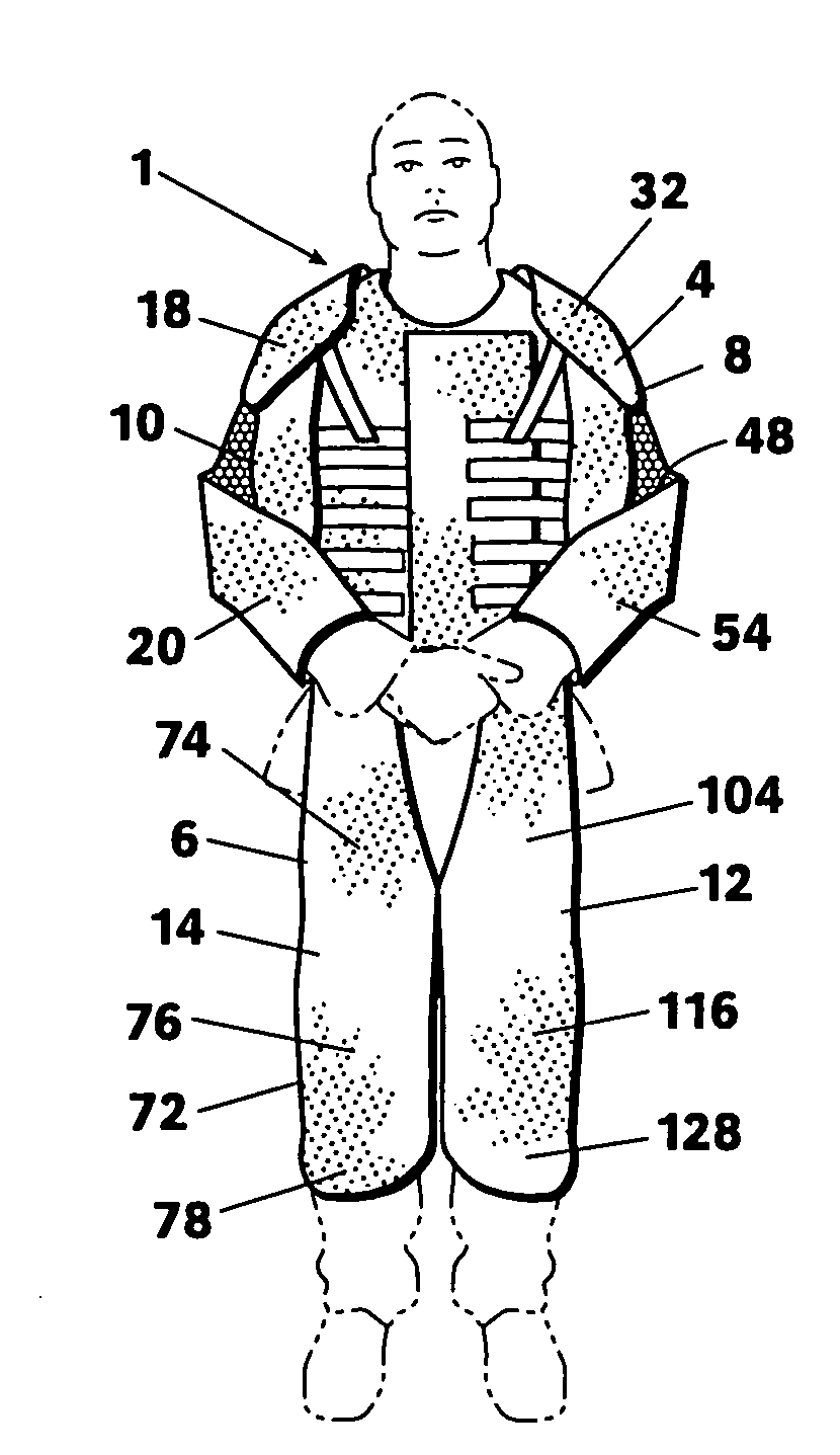
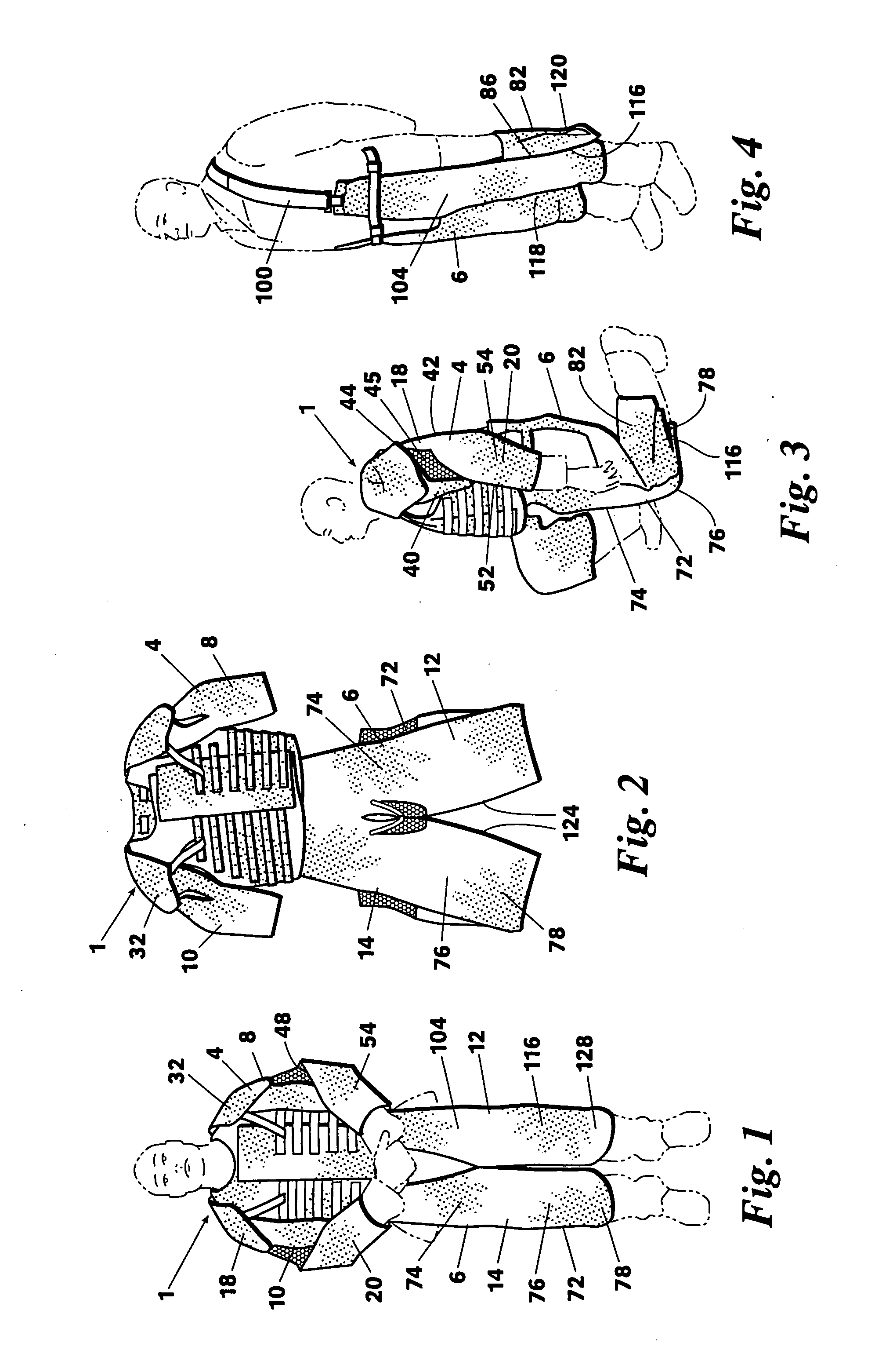
[0087]In embodiment 2, the lower arm ballistic insert 24′ preferably extends 360 degrees around the user's lower arm.

[0088]In embodiment 1, the lower arm ballistic insert 24 includes a first portion 50 which extends over the front 52, the outer side 54, and the inner side 56 of the user's lower arm but does not extend over the back 58 of the lower arm. The lower arm section 20 of embodiment 1 thus includes a lower arm ventilation zone 62 which does not include any ballistic material. The lower arm ventilation zone 62 of embodiment 1 is most preferably provided by forming a ventilation cutout 64 in the lower arm ballistic insert 24.

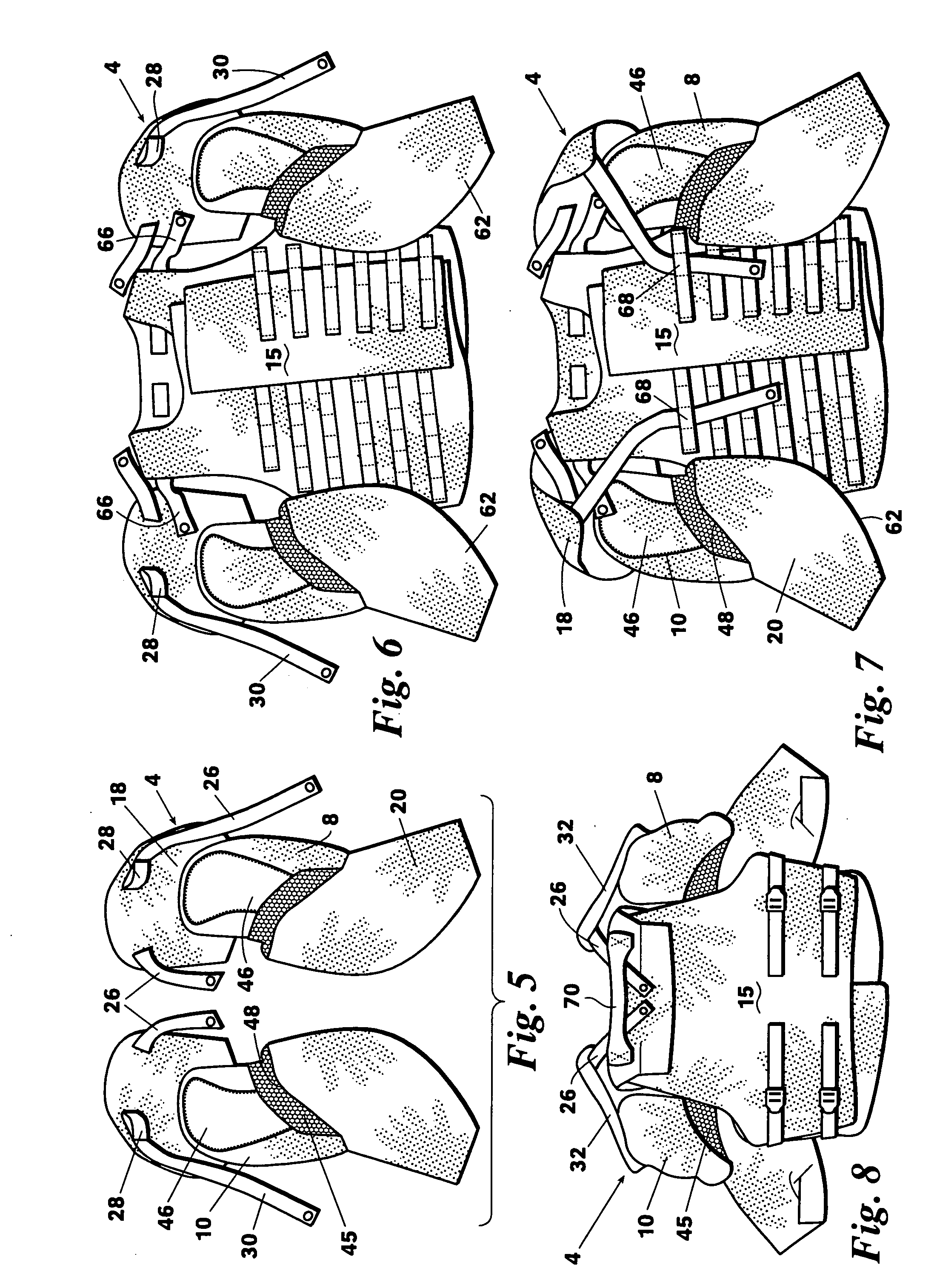
[0089]The use of the upper extremity protection system 4 of embodiment 1 with an outer tactical vest 15 is illustrated in FIGS. 5-8. The upper arm protection units 8 and 10 of embodiment 1 can be conveniently attached to the outer tactical vest 15 by: (a) sliding the vest epaulets 66 through the arm protection unit epaulet attachment loops 28 and snapping;...

embodiment 1

[0091]The ballistic material insert 80 for each of the leg protection units 12 and 14 of embodiment 1 includes: an upper portion 102 which covers at least the front portion 104 and the back portion 106 of the user's upper legs but does not extend over the inner portion of the upper leg; a knee portion 110 which will extend around the knee region of the user's leg but includes a cutout 112 which will be positioned on the back of the user's knee to provide flexibility for squatting, running, climbing, etc.; and a lower leg portion 114 which will extend over the outer side 116, the inner portion 118, and the back 120 of the user's lower leg but includes a ventilation cutout 122 which will be positioned on the front of the lower leg over the user's shin bone.

[0092]The ballistic material insert 80′ for each of the leg protection units 12′and 14′ of embodiment 2 is similar to insert 80 except that (a) the upper portion 102′ of the embodiment 2 insert 80′ will extend over at least most of ...


PUM


Abstract

Body armor for ballistic protection of a user's extremities preferably comprising right and left arm protection units and / or right and left leg protection units. The units include a ballistic protection material which preferably covers most of the user's upper arm, elbow region, lower arm, shoulder, upper leg, knee region, and lower leg except for ventilation zones preferably located on the inner portion of the upper arm and the inner part of the upper leg. The back of the knee is preferably covered by a protective flap.

Description

CROSS-REFERENCE TO RELATED APPLICATION[0001]This invention claims the benefit of co-pending U.S. Provisional Application Ser. No. 60 / 634,533 filed Dec. 10, 2004.FIELD OF THE INVENTION[0002]The present invention relates to body armor systems for ballistic protection of a user's extremities.BACKGROUND OF THE INVENTION[0003]The introduction of the outer tactical vest (OTV) with ceramic plates has shifted the apparent injury pattern of soldiers to make limb amputation more common. The superb effectiveness of the torso armor results in the survival of soldiers who, without the OTV, would have been killed. However, due to the closer proximity to the blast, the arms and legs are vulnerable. This situation was not anticipated so there does not exist today any total limb protection option for the foot soldier.[0004]There have been several partial options fielded just since June 2004, such as an underarm protector and shoulder protector. The US Army is fielding this option. The US Marine Corp...

Claims


Application Information

Patent Timeline
Patent Type & Authority Applications(United States)
IPC IPC(8): F41H1/02
CPCF41H1/02
Inventor MATIC, PETERHUBLER, GRAHAMSIMMONDS, KIRTHSPRAGUE, JAMESRUPERT, NEVINFROST, JOHN JOSEPHBRANSON, DONNAFARR, CHERYLPEKSOZ, SEMRABRUNO, RICHARD STEVEN
Owner USA AS REPRESENTED BY THE SEC OF THE NAVY THE
Why Eureka
Try Eureka