Apparatus and Method for Attenuating Acoustic Waves In Pipe Walls for Clamp-On Ultrasonic Flow Meter

a technology of ultrasonic flow meter and pipe wall, which is applied in the direction of instruments, measurement devices, scientific instruments, etc., can solve the problems of preventing the propagation of structural components to the receiver, and achieve the effect of increasing the flexural stiffness of the pipe and modifying the ultrasonic vibrational characteristics of the pip

Active Publication Date: 2008-05-01
EXPRO METERS
View PDF99 Cites 25 Cited by
  • Summary
  • Abstract
  • Description
  • Claims
  • Application Information

AI Technical Summary

Benefits of technology

[0008]In one embodiment, the damping structure includes a housing secured to the pipe to modify ultrasonic vibrational characteristics of the pipe by increasing a flexural stiffness of the pipe. In this regard, the housing contacts and reinforces selective areas of the pipe to provide a diaphragm including reinforced areas and unreinforced areas. The unreinforced areas are disposed about and in proximity to the transmitter and the receiver. In one embodiment, a resonant frequency of the diaphragm coincides with a resonant frequency of a maximum transmission of the ultrasonic signal.

Problems solved by technology

The damping structure dampens the structural component of the ultrasonic signal to impede propagation of the structural component to the receiver.

Method used


Image

  • Apparatus and Method for Attenuating Acoustic Waves In Pipe Walls for Clamp-On Ultrasonic Flow Meter
  • Apparatus and Method for Attenuating Acoustic Waves In Pipe Walls for Clamp-On Ultrasonic Flow Meter
  • Apparatus and Method for Attenuating Acoustic Waves In Pipe Walls for Clamp-On Ultrasonic Flow Meter

Examples


Embodiment Construction

[0043]The present invention discloses apparatus' and methods for reducing the impact of structural borne noise, an unintended by-product of launching a fluid borne ultrasonic interrogation signal, during the operation of clamp-on flow ultrasonic flow meters, as described in commonly owned, U.S. patent application Ser. No. 10 / 756,977, filed Jan. 13, 2004, which is incorporated herein by reference.

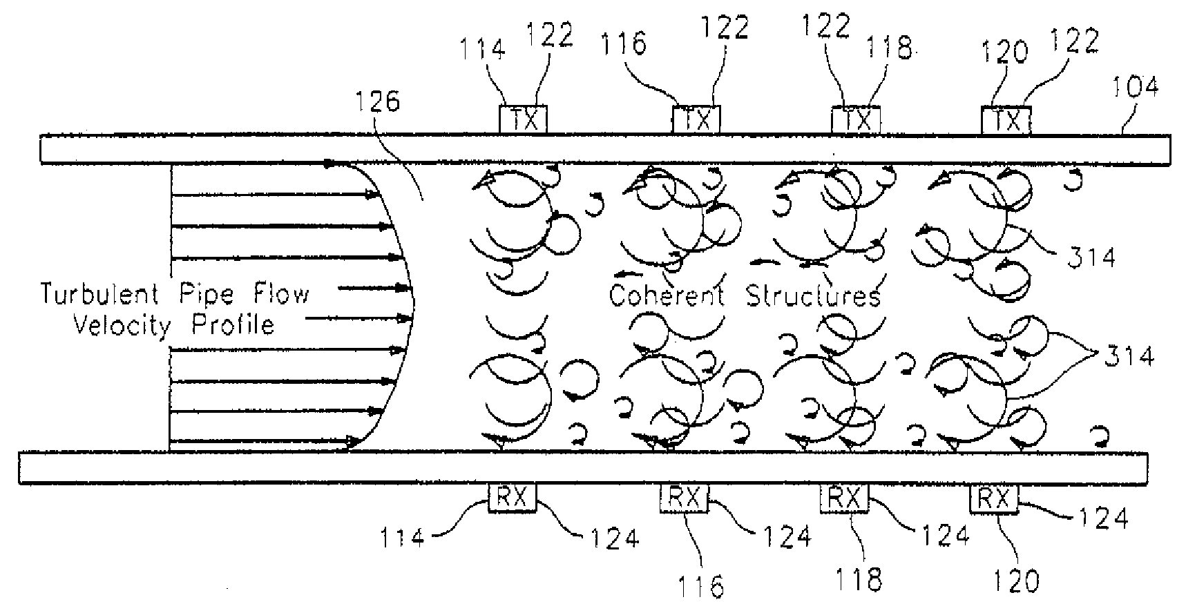
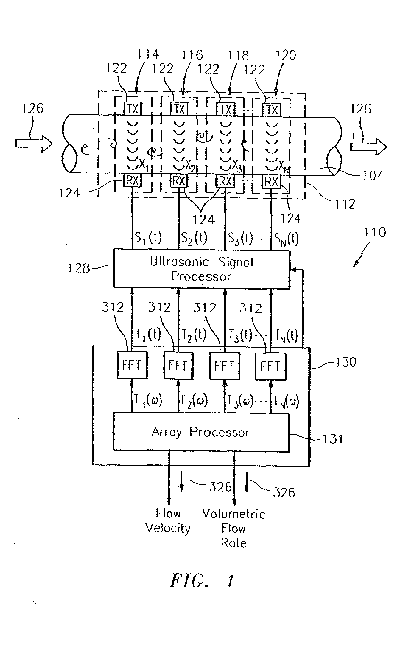
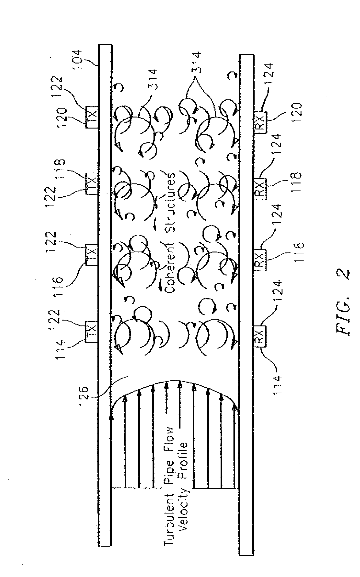
[0044]FIGS. 1 and 2 illustrate an ultrasonic clamp-on flow meter 110, as described in U.S. patent application Ser. No. 10 / 756,977, wherein the ultrasonic flow meter 110 includes an array of ultrasonic sensors 112 (e.g., a sensing device 112) having a plurality of ultrasonic sensors 114, 116, 118 and 120 disposed axially along the length of a pipe 104. Each ultrasonic sensor 114, 116, 118 and 120 comprises a transmitter (TX) 122 and a receiver (RX) 124 pair. The transmitter 122 provides an ultrasonic signal to the corresponding receiver 124, wherein the ultrasonic signal is orthogonal to a di...


PUM

PropertyMeasurementUnit
resonant frequenciesaaaaaaaaaa
diametersaaaaaaaaaa
diametersaaaaaaaaaa

Abstract

An apparatus is presented for damping an undesired component of an ultrasonic signal. The apparatus includes a sensor affixed to a pipe. The sensor includes a transmitter and a receiver. The transmitted ultrasonic signal includes a structural component propagating through the pipe and a fluid component propagating through a flow in the pipe. The receiver receives one of the transmitted components. The apparatus includes a damping structure. The damping structure dampens the structural component of the ultrasonic signal to impede propagation of the structural component to the receiver. The damping structure includes one of a housing secured to the pipe to modify ultrasonic vibrational characteristics thereof, a plurality of film assemblies including a tunable circuit to attenuate structural vibration of the pipe, and a plurality of blocks affixed to the pipe to either reflect or propagates through the blocks, the undesired structural component of the ultrasonic signal.

Description

[0001]This application claims the benefit of U.S. Provisional Patent Application Ser. No. 60 / 855,585, filed Oct. 30, 2006.CROSS-REFERENCE TO RELATED PATENT APPLICATIONS[0002]This application is also related to U.S. patent application Ser. No. 11 / 881,477, filed Jul. 27, 2007. The disclosures of these U.S. patent documents are incorporated by reference herein in their entireties.TECHNICAL FIELD[0003]This invention relates to a method and apparatus for attenuating acoustic waves (or ring around acoustics) propagating through the walls of a pipe for a clamp-on ultrasonic flow meter.BACKGROUND[0004]Most ultrasonic flow measurements seek to leverage information contained in fluid borne disturbances of a specific temporal frequency. The specific frequency often results from natural frequencies of the drive electronics, the transducer, or the resonant transmission characteristic of the pipe wall.[0005]Referring to FIG. 8, one of the primary challenges associated with clamp-on ultrasonic flo...

Claims


Application Information

Patent Timeline
Patent Type & Authority Applications(United States)
IPC IPC(8): G01N29/032G01F1/7082
CPCG01F1/7082G01F1/712G01N29/222G01N2291/048G01N2291/0421G01N2291/0422G01N2291/02836
Inventor FERNALD, MARKGYSLING, DANIEL L.BAILEY, TIMOTHY J.DANG, CHANGJIU
Owner EXPRO METERS
Why Eureka
Try Eureka