Electric punching device

a technology of electric punching and electric motor, which is applied in the direction of metal working devices, etc., can solve the problems of low efficiency of manual punching devices, insufficient punching strength of users, and user fatigue, and achieves low cost, good transfer performance and stability of structure, and small space occupation

Inactive Publication Date: 2008-05-01
SHENZHEN QIXIN GRP LLC
View PDF0 Cites 0 Cited by
  • Summary
  • Abstract
  • Description
  • Claims
  • Application Information

AI Technical Summary

Benefits of technology

[0014]An advantage of the present invention is that the motor and the motor bracket may cooperate with a gear, a lever, a strap or a chain, or the motor and the transmission shaft bracket may cooperate with the gear, the lever, the strap or the chain. When operating, the transfer performance and stability of the structure is good, and space occupied is small, cost is low.
[0015]To further understand features and technical contents of the present invention please refer to the following detailed description and drawings related the present invention. But the drawings are only used to be references and explanations, not be limits to the present invention.

Problems solved by technology

Although the manual punching devices are used widely, but users have to exert themselves to operate on the devices when they want to punch a pile of thick paper.
However, the users' strength is not great enough to punch any holes sometimes, so the efficiency of such manual punching devices is low somewhat, and the users are prone to be tired.
On the other hand, the known electric punching device' structure is complicated, volume is large, space occupied is also large, cost is high, and transfer performance is poor, stability of structure is low.

Method used


Image

  • Electric punching device
  • Electric punching device
  • Electric punching device

Examples


third embodiment

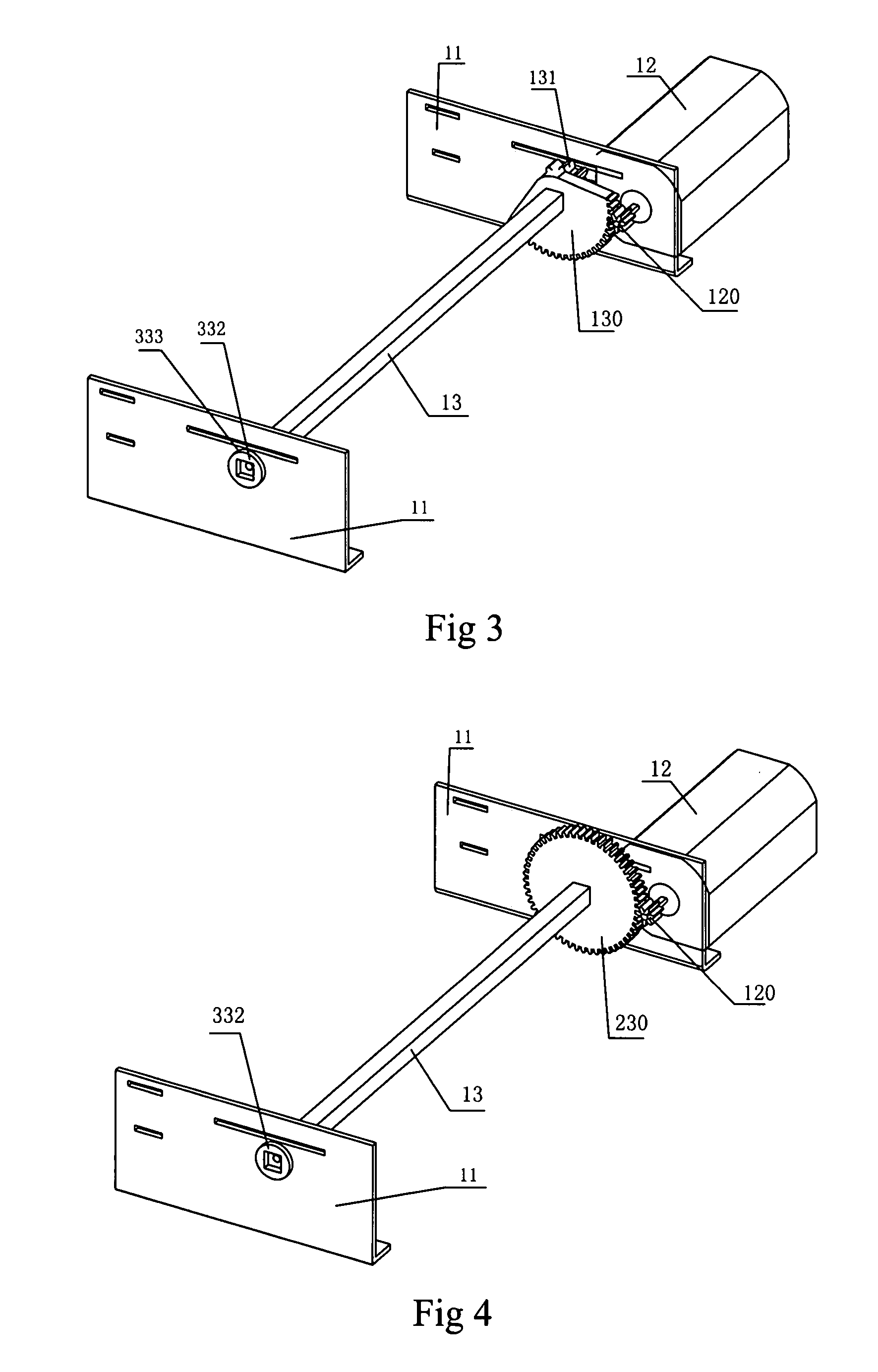
[0035]Differ from FIG. 1, the position of the motor 12 and the transmission component relative to the transmission shaft brackets 11 of the third embodiment shown in FIG. 3 is exchanged, that is to say, the motor 12 is set outside the transmission shaft bracket 11 and the driving gear 120 and the driven gear 130 are set inside the transmission shaft bracket 11.

fourth embodiment

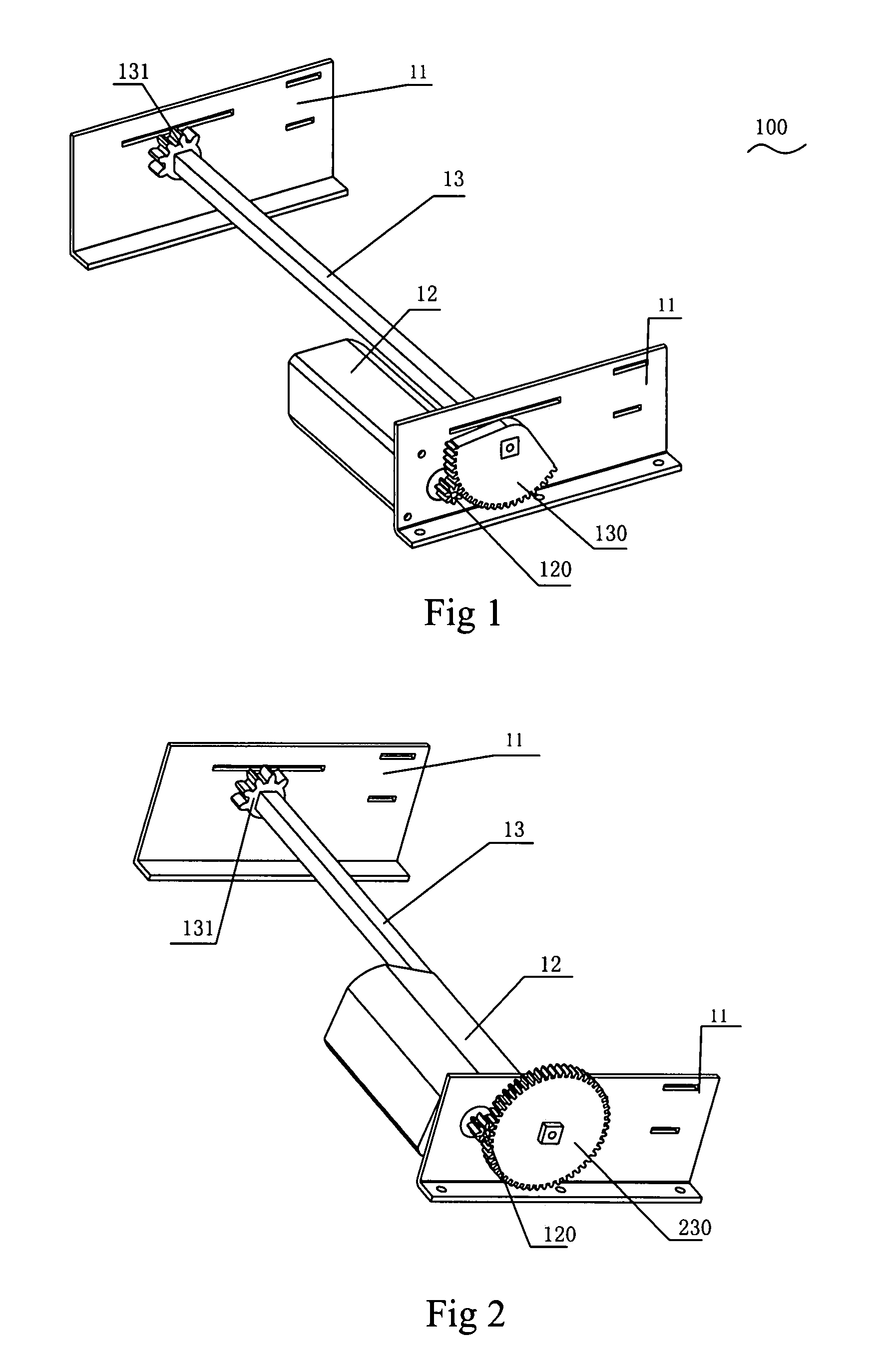
[0036]Differ from FIG. 3, the driven gear 230 of the fourth embodiment shown in FIG. 4 is an all gear.

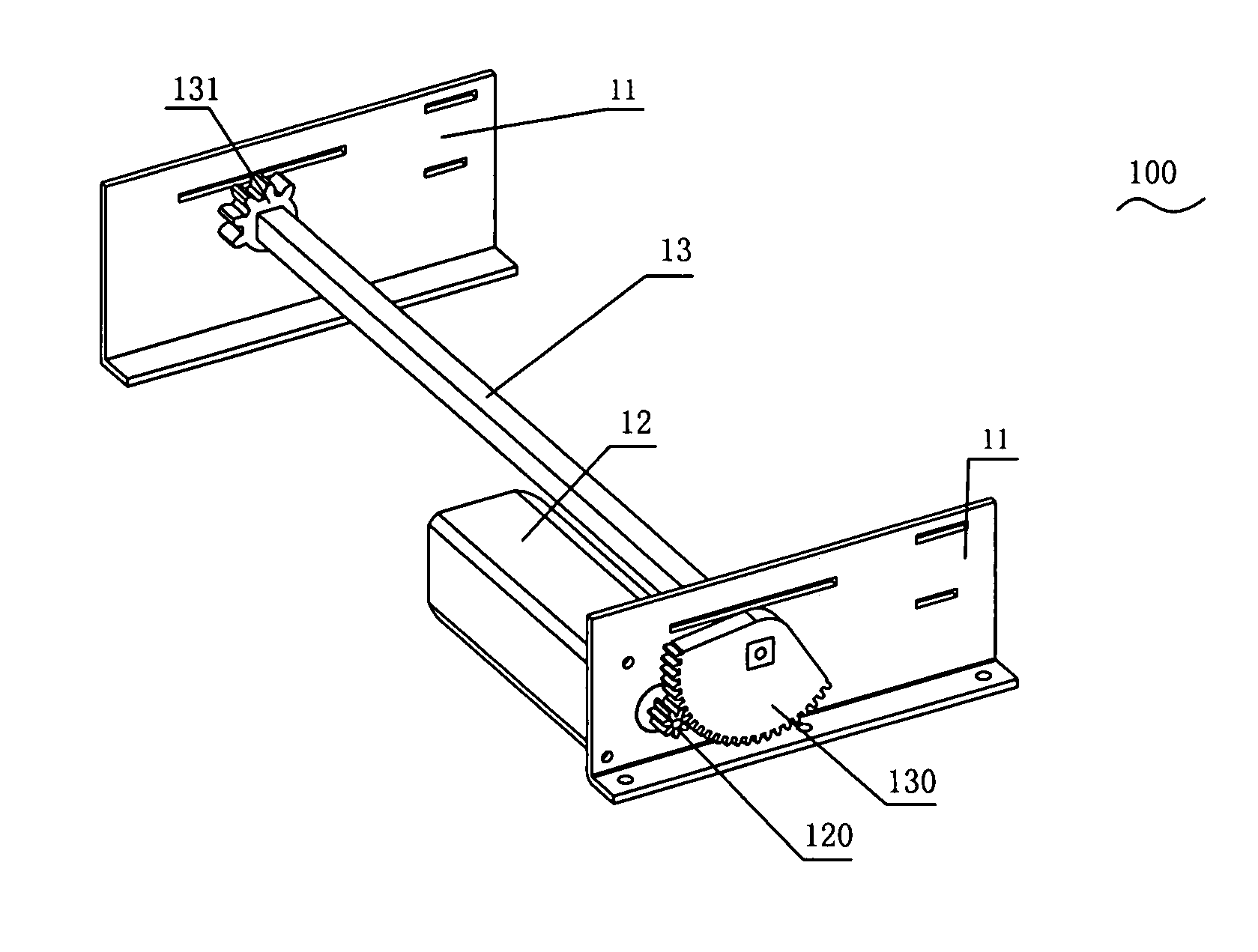
[0037]Please referring to FIG. 5 and FIG. 6, a motor bracket 50 is added in the driving transmission frame 100. The motor 12 is set on the motor bracket 50. In FIG. 5, the motor bracket 50 lies outside one of the transmission shaft brackets 11, the motor 12 is fixed on the motor bracket 50, the driving gear 120 is set between the motor bracket 50 and the transmission shaft bracket 11, the driven gear 130 is fixed on the transmission shaft 13 between the motor bracket 50 and the transmission shaft bracket 11, the driving gear 120 joggles with the driven gear 130, and the driving gear 120 is a cylindrical gear and the driven gear 130 is but not limited to one third gear. The ends of the transmission shaft 13 are fixed by the gear sheath 131. The driving transmission principle of the embodiment is: the motor 12 is fixed on the motor bracket 50, the motor 12 drives the driving gear 120,...

sixth embodiment

[0038]Differ from FIG. 5, the driven gear 230 of the sixth embodiment shown in FIG. 6 is an all gear.


PUM

PropertyMeasurementUnit
thickaaaaaaaaaa
strengthaaaaaaaaaa
volumeaaaaaaaaaa

Abstract

An electric punching device includes a driving transmission frame, a group of reamers and a driving board. The group of reamers are set on the driving board. The driving transmission frame includes a driving device and a transmission device, and the driving device includes a transmission shaft, a transmission shaft bracket and a transmission device and the transmission device is driven by a motor and drives the transmission shaft to turn. The motor and a motor bracket may cooperate with a gear, a lever, a strap or a chain, or the motor and the transmission shaft bracket may cooperate with the gear, the lever, the strap or the chain. When operating, the transfer performance and stability of the structure is good, space occupied is small, and cost is low.

Description

BACKGROUND OF THE INVENTION[0001]1. Field of the invention[0002]The present invention relates to an electric punching device belonged to office supplies, and more especially to a transmission frame of the electric punching device for driving.[0003]2. Description of the Prior Art[0004]At present, punching devices are used to punch on files or loose-leaves and include manual punching devices and electric punching devices. Although the manual punching devices are used widely, but users have to exert themselves to operate on the devices when they want to punch a pile of thick paper. However, the users' strength is not great enough to punch any holes sometimes, so the efficiency of such manual punching devices is low somewhat, and the users are prone to be tired. On the other hand, the known electric punching device' structure is complicated, volume is large, space occupied is also large, cost is high, and transfer performance is poor, stability of structure is low.[0005]Hence, inventors...

Claims


Application Information

Patent Timeline
Patent Type & Authority Applications(United States)
IPC IPC(8): B26D1/12
CPCB26D5/08B26F1/34Y10T83/9387
Inventor CHEN, QINQI
Owner SHENZHEN QIXIN GRP LLC
Why Eureka
Try Eureka