Method and apparatus for photomask plasma etching

a plasma etching and photomask technology, applied in the direction of vacuum evaporation coating, coating, electric discharge tube, etc., can solve the problems of increasing complexity in the design and fabrication of advanced technology photomasks

Active Publication Date: 2008-05-01
APPLIED MATERIALS INC
View PDF90 Cites 320 Cited by
  • Summary
  • Abstract
  • Description
  • Claims
  • Application Information

AI Technical Summary

Benefits of technology

[0008]The present invention generally provides a method and apparatus for etching photomasks. One embodiment provides an apparatus for plasma etching that includes a process chamber, a substrate support pedestal in the process chamber, an RF power source for forming a plasma within the chamber, a shield disposed in the chamber above the pedestal and below a plasma forming region in the chamber, the shield configured to control a distribution of ionic and neutral species of the plasma, at least one gas inlet for providing a gas flow into the chamber, and a deflector plate assembly disposed above the shield, the deflector plate assembly configured to provide a predetermined gas flow pattern between the gas inlet and the shield.

Problems solved by technology

With ever-decreasing device dimensions, the design and fabrication of photomasks for advanced technology becomes increasingly complex, and control of critical dimensions and process uniformity becomes increasingly more important.

Method used


Image

  • Method and apparatus for photomask plasma etching
  • Method and apparatus for photomask plasma etching
  • Method and apparatus for photomask plasma etching

Examples


Embodiment Construction

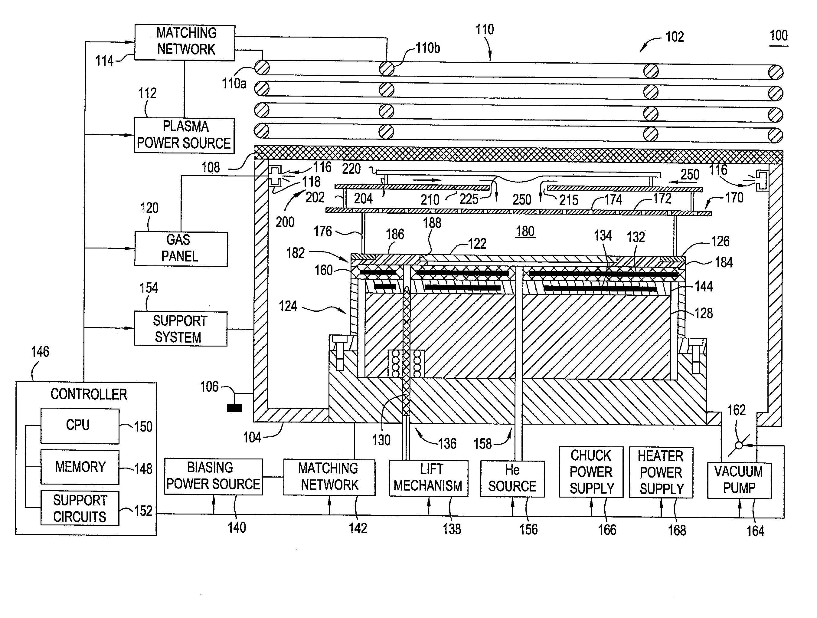
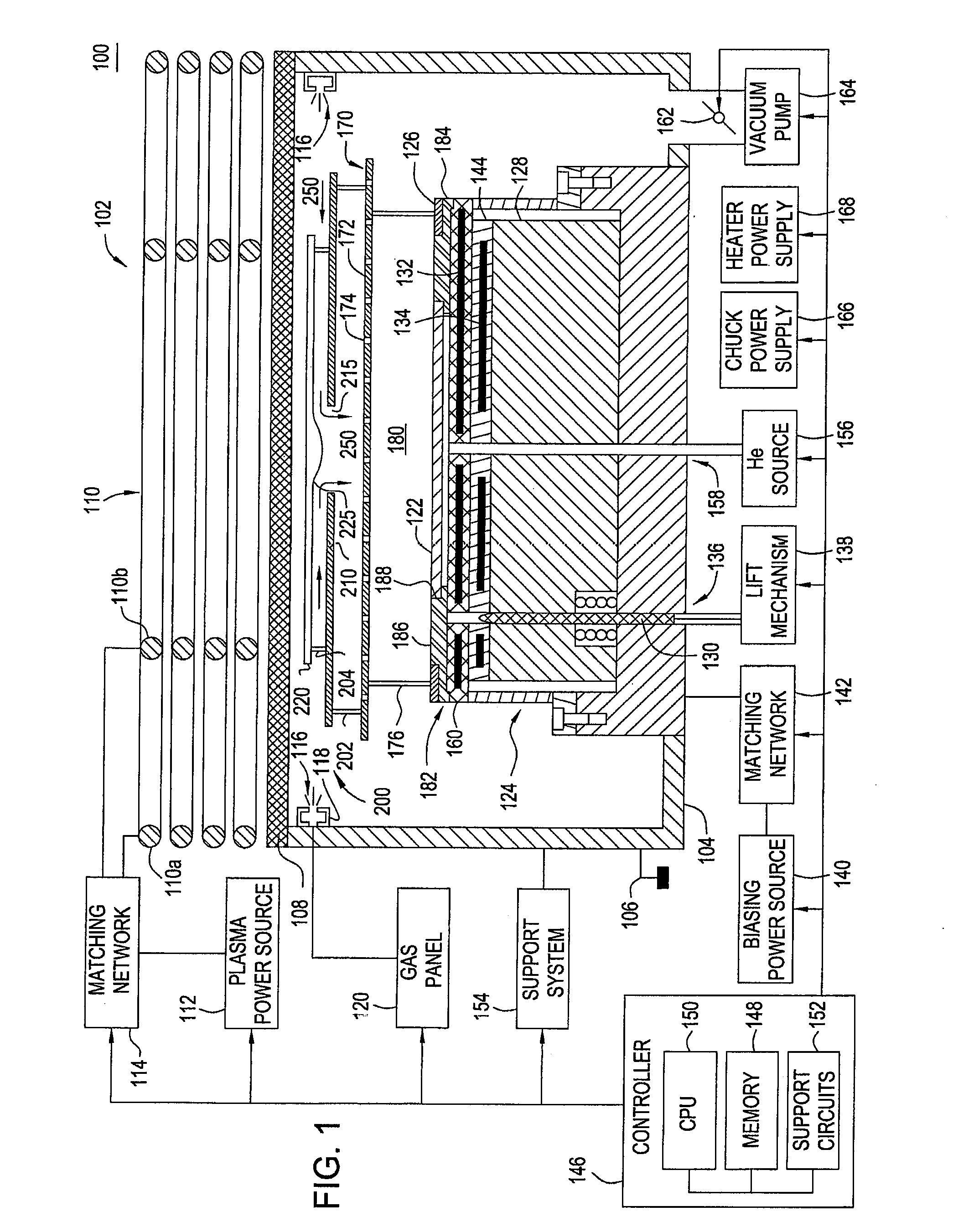
[0020]The present invention provides a method and apparatus for etching of a photomask substrate by providing improved control of the gas flow pattern and plasma uniformity. The apparatus includes a deflector plate assembly configured to control the radial and vertical components of a gas flow provided in the processing chamber. The deflector plate assembly is disposed above the substrate. In one embodiment, a shield, also referred to as an ion-radical shield or ion-neutral shield, is disposed between the deflector plate assembly and the substrate. A plasma is formed in a quasi-remote, upper processing region of the chamber above the shield, which is configured for controlling the distribution of charged and neutral species in the chamber during processing.

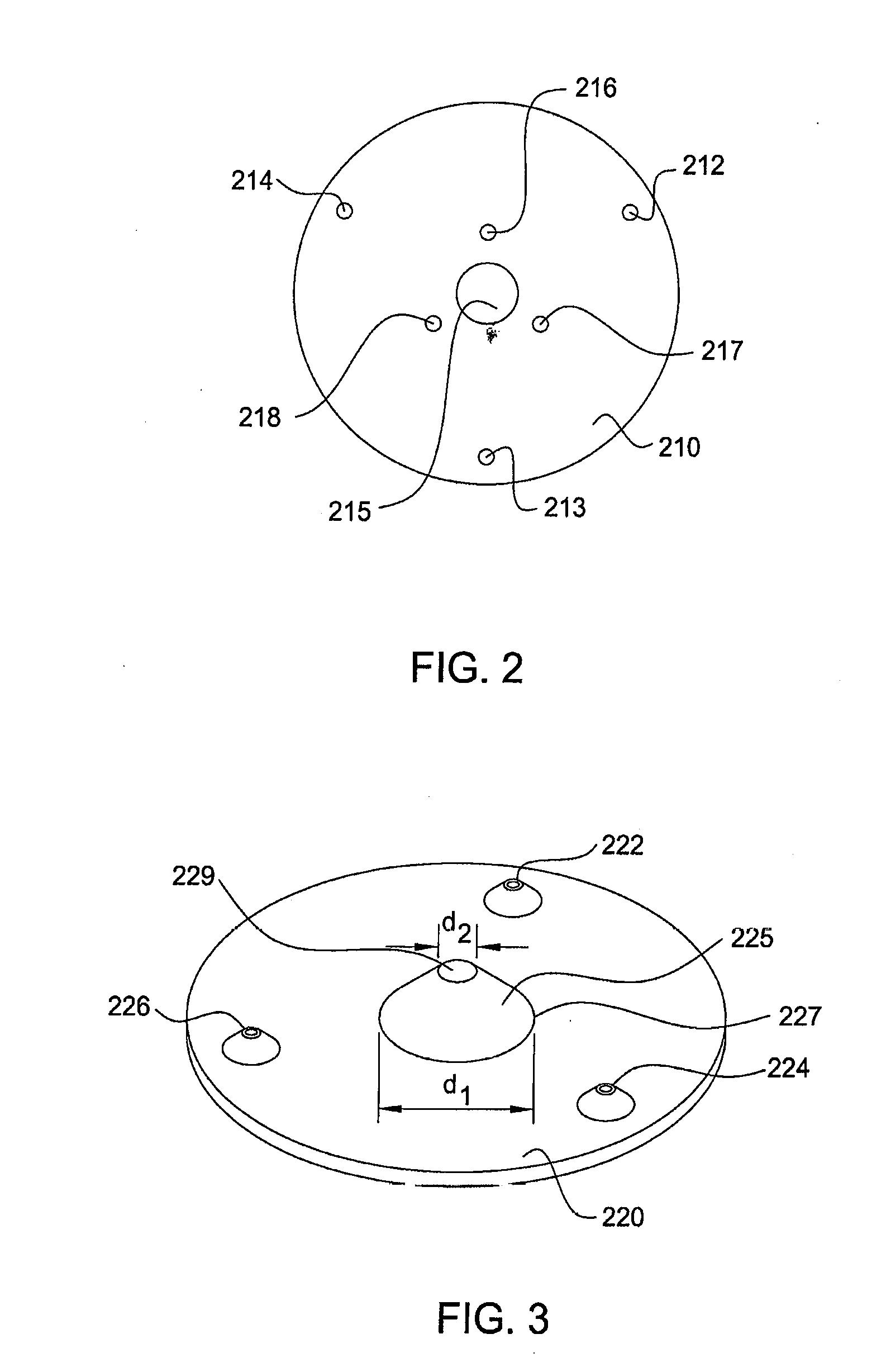
[0021]In another embodiment, the deflector plate assembly is used to redirect the flow of gases in the processing chamber. One embodiment of the deflector plate assembly comprises a first plate having an aperture, whose location a...


PUM

PropertyMeasurementUnit
diameteraaaaaaaaaa
dielectric constantaaaaaaaaaa
frequencyaaaaaaaaaa

Abstract

A method and apparatus for etching photomasks is provided herein. In one embodiment, the apparatus comprises a process chamber having a support pedestal adapted for receiving a photomask. An ion-neutral shield is disposed above the pedestal and a deflector plate assembly is provided above the ion-neutral shield. The deflector plate assembly defines a gas flow direction for process gases towards the ion-neutral shield, while the ion-neutral shield is used to establish a desired distribution of ion and neutral species in a plasma for etching the photomask.

Description

CROSS-REFERENCE TO RELATED APPLICATIONS[0001]The subject matter of this application is related to the subject matter disclosed in U.S. patent application Ser. No. 10 / 880,754, entitled “METHOD AND APAPRATUS FOR QUASI-REMOTE PLASMA ETCHING”, filed on Jun. 30, 2004, by Todorow, et al. (Attorney Docket No. APPM / 7716), and in U.S. patent application Ser. No. 10 / 882,084, entitled “METHOD AND APAPRATUS FOR PHOTOMASK PLASMA ETCHING”, filed on Jun. 30, 2004, by Kumar, et al. (Attorney Docket No. APPM / 9400), and in U.S. patent application Ser. No. ______, entitled “METHOD AND APAPRATUS FOR PHOTOMASK PLASMA ETCHING”, filed concurrently herewith, by Kumar, et al. (Attorney Docket No. APPM / 11454), all of which are hereby incorporated herein by reference in its entirety.BACKGROUND OF THE INVENTION[0002]1. Field of the Invention[0003]Embodiments of the present invention generally relate to a method and apparatus for plasma etching photomasks and, more specifically, to a method and apparatus with i...

Claims


Application Information

Patent Timeline
Patent Type & Authority Applications(United States)
IPC IPC(8): H01L21/3065
CPCH01J37/32422H01J37/32449H01J37/3244H01L21/3065
Inventor KUMAR, AJAYCHANDRACHOOD, MADHAVI R.LEWINGTON, RICHARDBIVENS, DARINSABHARWAL, AMITABHPANAYIL, SHEEBA J.OUYE, ALAN HIROSHI
Owner APPLIED MATERIALS INC
Why Eureka
Try Eureka