
Method for controlling microstructure via thermally managed solid state joining

a microstructure and solid state joining technology, applied in the field of solid state welding technology, can solve problems such as increased susceptibility to cracking and other defect generation, unacceptable property degradation, and poor quality of weld joints, and achieve poor mechanical strength and toughness

Inactive Publication Date: 2008-05-01
GENERAL ELECTRIC CO
View PDF9 Cites 66 Cited by
  • Summary
  • Abstract
  • Description
  • Claims
  • Application Information

AI Technical Summary

Benefits of technology

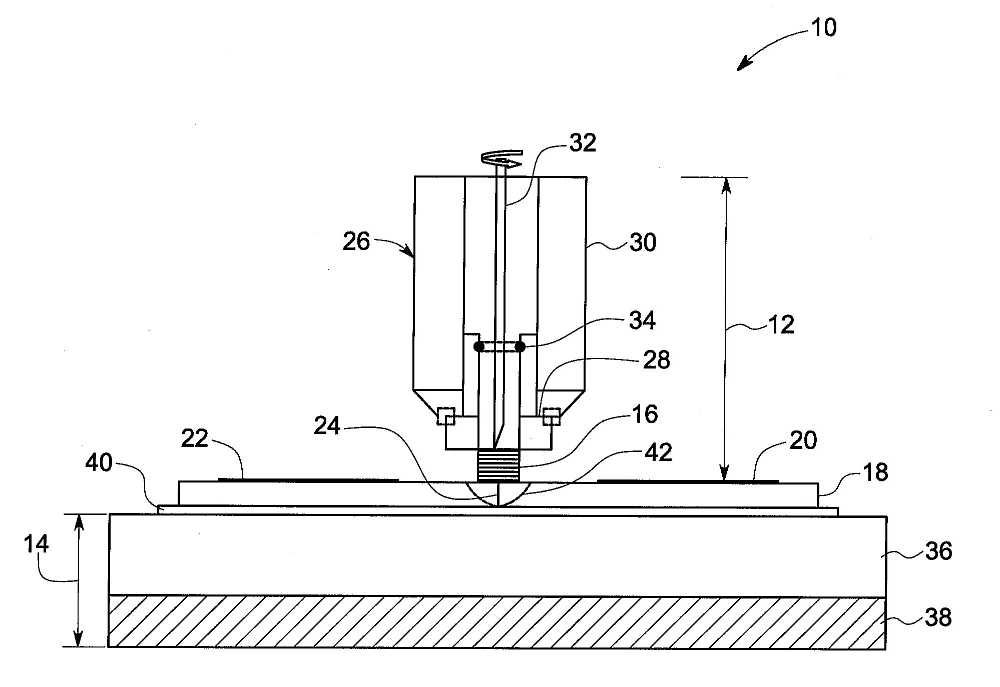
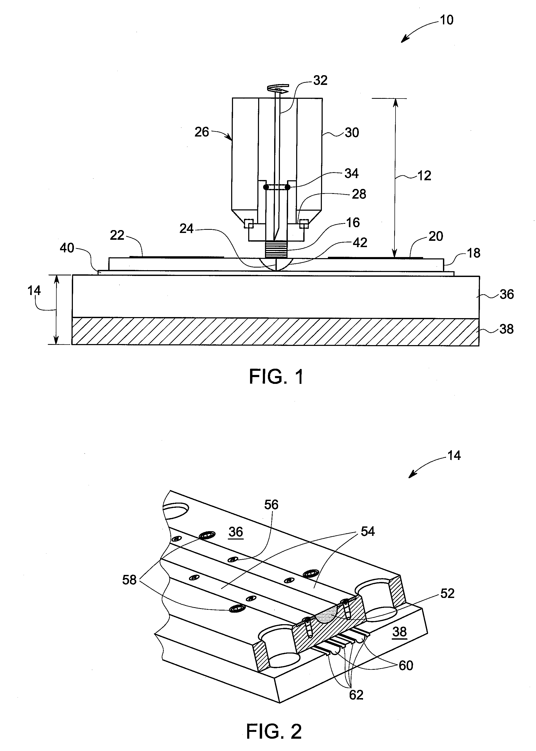
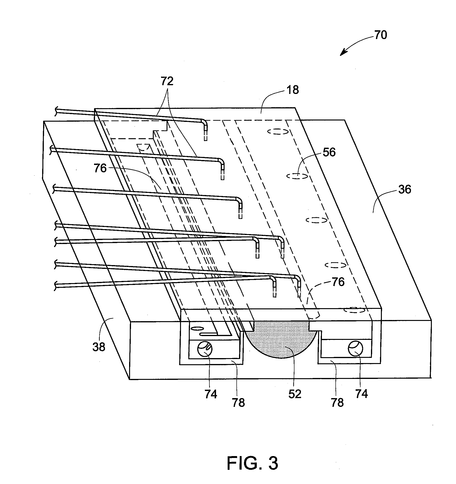
The invention provides a method for creating a solid state joint using an adjoining apparatus that includes a tool, a backing plate, and a thermal control plate. The method involves rotating the tool and controlling the temperature of the tool and backing plate to control the temperature and rate of change of temperature experienced by the workpiece, and to enable pre-weld, post-weld, and in-situ control over the thermal profile at the joint. The method also includes maintaining a user chosen temperature differential between the weld-affected zone and the backing plate via the thermal control plate. The invention also provides a method of operation for monitoring the temperature of the weld-affected zone and applying a temperature control based upon the monitored temperature. The method involves maintaining the temperature to about 50 to about 80 percent of melting temperature of the workpiece.

Problems solved by technology

However, an increased susceptibility to cracking and other defect generation, including unacceptable property degradation, was observed in such materials when joined by conventional welding technology.
The high temperatures in the tool, in combination with relatively high pre weld workpiece heating rates and high post-weld workpiece cooling rates, may result in a weld joint of poor quality, such as poor mechanical strength and toughness often but not always attributable to defects, undesirable material structure, and workpiece distortions.

Method used


Image

  • Method for controlling microstructure via thermally managed solid state joining
  • Method for controlling microstructure via thermally managed solid state joining
  • Method for controlling microstructure via thermally managed solid state joining

Examples


Embodiment Construction

[0015]As discussed in detail below, embodiments of the present invention provide a method for controlling microstructure and hence improving properties of a material during a solid state joining technique via thermal management of the material through controlled use of the welding apparatus. Some non-limiting examples of the properties of a material in solid state joints include yield strength, ultimate tensile strength, ductility, impact toughness, fracture toughness, fatigue crack growth resistance, low cycle fatigue resistance, high cycle fatigue resistance, and superplastic formability. In an example, the solid state joining includes a friction stir welding technique. The friction stir welding technique may be used to join one or more similar or dissimilar materials forming a workpiece. Some non-limiting examples of materials include metals, metal alloys, and thermoplastics. The term ‘controlling microstructure’ used herein refers to non-limiting examples such as controlling gra...


PUM

PropertyMeasurementUnit
lengthaaaaaaaaaa
lengthaaaaaaaaaa
diameteraaaaaaaaaa

Abstract

A method for creating a solid state joint is disclosed. The method includes providing an adjoining apparatus that includes a pin tool, a backing plate and a thermal control plate disposed below the backing plate. The method also includes rotating the pin tool and traversing the pin tool relative to a workpiece along a joint to be welded on the workpiece. The method further includes manipulating the temperature of the pin tool and the backing plate in order to control the temperature and rate of change of temperature experienced by the workpiece at a weld affected zone at the joint. The method also includes maintaining a user chosen temperature differential between the weld affected zone and the backing plate via the thermal control plate.

Description

BACKGROUND[0001]The invention relates generally to solid state welding technology, and more particularly to friction welding.[0002]In recent years, there has been a considerable effort put into designing and building powerful and efficient turbo-machinery such as gas turbine engines. The design involves use of materials having properties such as enhanced high temperature performance and strength, or advantageous strength-to-weight ratios. However, an increased susceptibility to cracking and other defect generation, including unacceptable property degradation, was observed in such materials when joined by conventional welding technology.[0003]Solid state welding or joining processes have been developed as a way of addressing these issues. One of the more successfully employed techniques is friction stir welding. Friction stir welding is regularly used to join metals and metal alloys. The friction stir welding technique overcomes a number of problems associated with other more convent...

Claims


Application Information

Patent Timeline
Patent Type & Authority Applications(United States)
IPC IPC(8): B23K20/12
CPCB23K20/122B29C66/91935B23K37/06B29C65/0681B29C66/1142B29C66/43B29C66/90B29C66/91216B29C66/91221B29C66/91421B29K2101/12B23K20/126B29C66/91645B29C66/961B29C66/91212B29C66/91411B29C65/00B29C66/91931B29C65/08B29C65/1425B29C65/16B29C65/18B29C65/224B29C65/26B29C66/0242B29C66/034B29C66/343B29C66/73921B29C66/8122B29C66/81264B29C66/81429B29C66/8167B29C66/836B29C66/81811B29K2905/12
Inventor HANLON, TIMOTHYSUBRAMANIAN, PAZHAYANNUR RAMANATHANHELDER, EARL CLAUDETRAPP, TIMOTHY JOSEPH
Owner GENERAL ELECTRIC CO
Learn More