Foam for mitigation of flow assurance issues in oil & gas systems

a technology of oil & gas system and flow assurance, applied in the field of foam, can solve the problems of less liquid inventory in the pipeline and lower pressure loss, and achieve the effects of avoiding the associated upset in production, reducing or even eliminating the use of corrosion inhibitors and their corresponding application procedures, and eliminating looped pigging lines

Inactive Publication Date: 2008-05-01
CHEVROU USA INC
View PDF4 Cites 1 Cited by
  • Summary
  • Abstract
  • Description
  • Claims
  • Application Information

AI Technical Summary

Benefits of technology

[0008]In some such method embodiments, the transport pipe can be completely or only partially filled with foam, depending on the specific properties and conditions of the associated application. Completely filled pipe ensures a homogeneous plug flow regime along the line, whereas intermittent foam plugs can sweep liquid from the pipeline more efficiently than gas alone, thereby resulting in less liquid inventory in the pipeline and lower pressure loss. Furthermore, a partially-filled pipe modifies the flow map of the system—thereby increasing the apparent volume of liquid in the pipe.
[0009]In start-up operations, formation of foam can permit a more effective removal of condensate that may have accumulated along the pipeline. Additionally, in shut-down operation, foaming can allow for uniform dispersion and mixing of any inhibitor necessary for a particular application / process.
[0010]In some embodiments, the present invention is directed to systems for transporting foam through a transport pipe, i.e., systems for implementing the above-described methods, the systems comprising: (a) a transport pipe for transporting hydrocarbon fluids (e.g., gas-dominated hydrocarbon fluids); (b) a means for generating a foam, wherein the foam is either a hydrocarbon-based foam or a water-based foam; (c) a means for transporting said foam a distance through the transport pipe; and (d) a means for destabilizing or “breaking” the foam subsequent to it being transported through the transport pipe.
[0011]Such above-described methods and systems generally provide for substantial improvement over existing methods for providing flow assurance, particularly with respect to the pipe transport of gas-dominated hydrocarbon fluids and their more universal applicability in addressing flow assurance issues.
[0012]The foregoing has outlined rather broadly the features of the present invention in order that the detailed description of the invention that follows may be better understood. Additional features and advantages of the invention will be described hereinafter which form the subject of the claims of the invention.

Problems solved by technology

Completely filled pipe ensures a homogeneous plug flow regime along the line, whereas intermittent foam plugs can sweep liquid from the pipeline more efficiently than gas alone, thereby resulting in less liquid inventory in the pipeline and lower pressure loss.

Method used


Image

  • Foam for mitigation of flow assurance issues in oil & gas systems
  • Foam for mitigation of flow assurance issues in oil & gas systems
  • Foam for mitigation of flow assurance issues in oil & gas systems

Examples


process embodiments

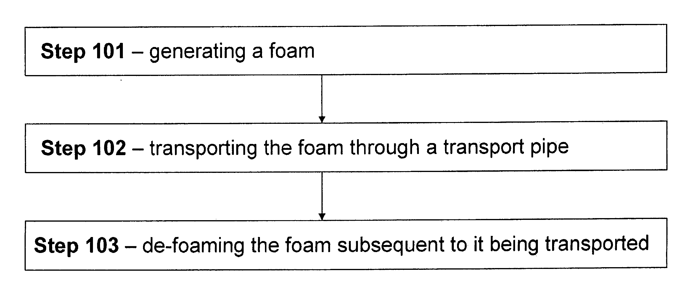
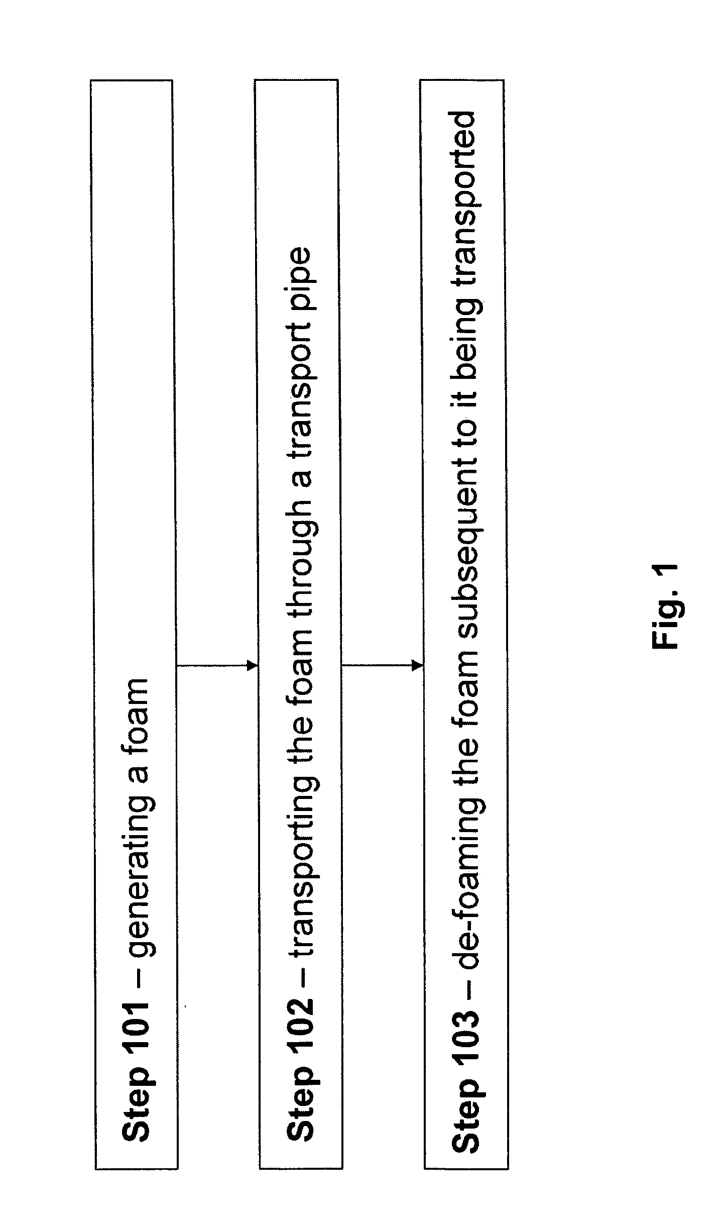
[0022]Referring to FIG. 1, in some embodiments, the present invention is directed to methods comprising the steps of: (Step 101) generating a foam selected from the group consisting of an oil-based foam and / or a water-based foam; (Step 102) transporting said foam a distance through a transport pipe, wherein the transport pipe is used for transporting hydrocarbon fluids; and (Step 103) de-foaming said foam subsequent to it being transported. Such methods are generally representative of the “foam flow process” presented herein. Moreover, the hydrocarbon fluids so transported are typically gas-dominated.

[0023]Generally, the foam is generated from foam precursor(s). In some presently-contemplated embodiments, the foam comprises the hydrocarbon fluid that the pipe transports. That is, the hydrocarbon fluid serves as a foam precursor. In some such embodiments, all or part of the hydrocarbon fluid is at least partially transported as a foam within the associated pipeline.

[0024]In some such...

example 1

[0044]This Example serves to illustrate a process and corresponding system for generating foam in situ (i.e., in-line), in accordance with some embodiments of the present invention.

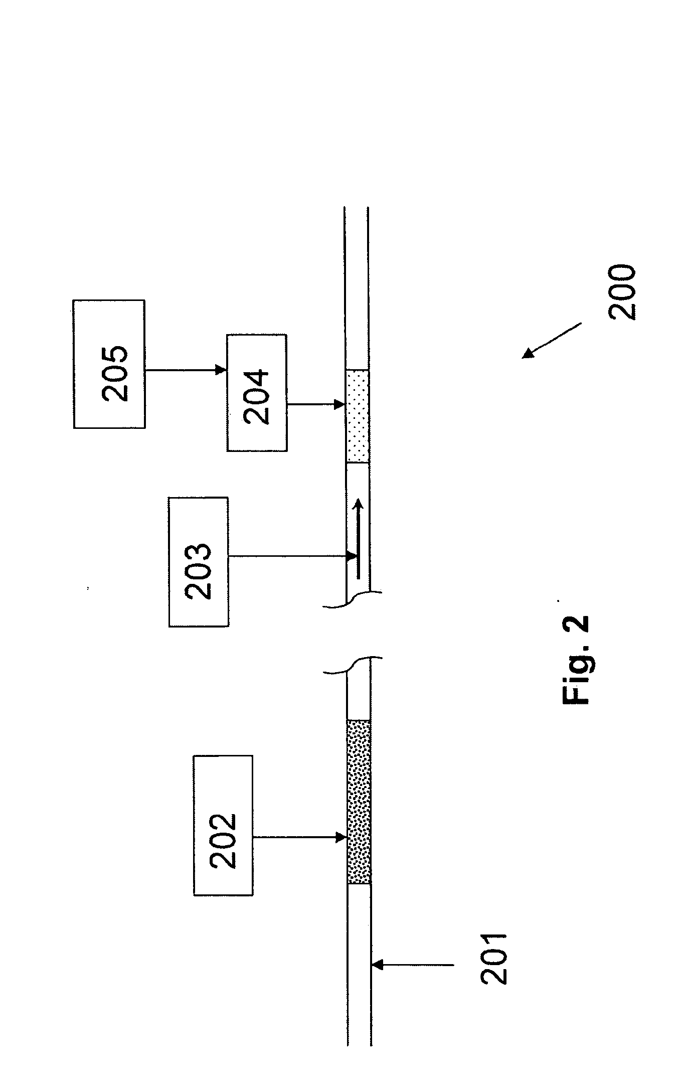
[0045]Referring to FIG. 3, depicting exemplary system 300, a gas-dominated hydrocarbon fluid flows through transport pipe 301 where, upon reaching region 304, foam is generated by a means 302. In this embodiment, the foam comprises the hydrocarbon fluid and the foam generation means is separable from the fluid flow by valve 303, so as to permit either continuous or intermittent foaming of the hydrocarbon fluid. In this embodiment, foaming is carried out in-line in region 304 using a mixing means and a foaming additive supplied from means 302. The foam then travels to region 307 where it is de-foamed by de-foaming means 305, which is separable from region 307 by valve 306. In this embodiment, the foamed hydrocarbon fluid is destabilized by addition of a de-foaming agent, dilution agent, heat, and / or mechan...

example 2

[0046]This Example serves to illustrate a process and corresponding system for generating foam in an auxiliary side stream with subsequent injection into the main transport pipeline (i.e., the main stream), in accordance with some embodiments of the present invention.

[0047]Referring to FIG. 4, depicting an alternative exemplary system 400, a gas-dominated hydrocarbon fluid flows through transport pipe 401 where, upon reaching valve 402, it is directed to auxiliary side stream 403 and foamed by a foaming means 404. In this embodiment, a foaming agent is added to the hydrocarbon fluid via foaming means 404 to create a hydrocarbon-based foam. The foam then re-enters the transport pipe 401 through valve 405 and is transported a distance through the pipe until it reaches valve 406. Upon reaching valve 406, the hydrocarbon-based foam is directed into side stream 407 and de-foamed by de-foaming means 408. In this embodiment, a de-foaming agent is introduced via de-foaming means 408. Upon b...


PUM

PropertyMeasurementUnit
distanceaaaaaaaaaa
pressureaaaaaaaaaa
Pressure dropaaaaaaaaaa

Abstract

The present invention is generally directed to methods and systems for mitigating flow assurance issues that arise in the pipe transport of hydrocarbon fluids, particularly wherein such hydrocarbon fluids are gas-dominated. Generally, such methods and systems rely on the formation and subsequent transport of a foam through an associated transport pipe.

Description

FIELD OF THE INVENTION[0001]This invention relates generally to oil and gas flow assurance issues, and specifically to methods and systems for improving flow characteristics in a hydrocarbon fluid pipeline via the formation of foam.BACKGROUND OF THE INVENTIONFlow Assurance[0002]Flow assurance is of considerable importance in the transport of hydrocarbon-based fluids through pipelines. Flow assurance issues include deposits (e.g., asphaltene, wax, hydrates, etc.) and, particularly in the case of gas-dominated hydrocarbon fluids, slippage between the gas phase and the liquid phase. Such latter issues are at least partially responsible for pressure losses and severe slugging problems, and they can contribute to sand deposition.[0003]While no universal method exists in the art for comprehensively addressing all of the above-listed flow assurance issues, methods have been developed that partially address these issues. For example, “pigging” is used to clean and inspect pipelines. Additio...

Claims


Application Information

Patent Timeline
Patent Type & Authority Applications(United States)
IPC IPC(8): C08J9/00
CPCF17D1/08B08B3/003C08J9/00
Inventor KOUBA, GENE E.MONTESI, ALBERTORHYNE, LEE D.
Owner CHEVROU USA INC
Why Eureka
Try Eureka