
Touch panel input device

a technology of input device and touch panel, which is applied in the field of touch panel input device, can solve the problems of significant degrading of detecting precision and increasing the cost of extra processing, and achieve the effects of high resolution, low detecting precision and wide output electrostatic capacitan

Inactive Publication Date: 2008-05-01
HOSIDEN CORP
View PDF1 Cites 52 Cited by
  • Summary
  • Abstract
  • Description
  • Claims
  • Application Information

AI Technical Summary

Benefits of technology

[0007] The present invention is contrived in view of the background of the art described above and aims to provide a touch panel input device modified so that the detecting precision does not significantly lower even if electrode areas and the like become small.
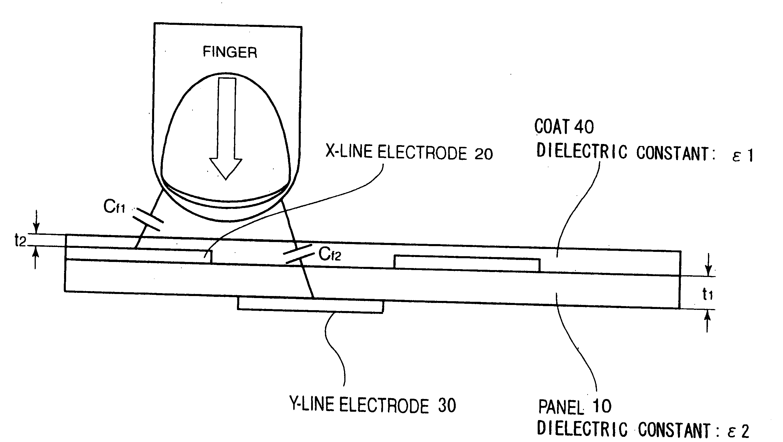
[0009] When touching the device with a finger, electrostatic capacitance generated between the first electrode and the finger is substantially on the same level as electrostatic capacitance generated between the second electrode and the finger. Therefore, the device can output electrostatic capacitance in a wide range of variation, and the detecting precision does not significantly lower even if the electrode area or the pitch interval becomes small to meet demand for higher resolution. Therefore, signal processing such as amplification and filtering becomes unnecessary, and cost can be reduced.
[0011] If a single sheet of transparent plate is used, the panel will enjoy high transparency, no occurrence of Newton's rings, ease in bending. Furthermore, such panel may lead to reduced costs and weight.

Problems solved by technology

However, in the above conventional art example, if the areas of X-line electrodes and Y-line electrodes or the pitch intervals between them reduce in accordance with demand for higher resolution, the range of variations in electrostatic capacitance that is output when the finger touches becomes narrow, significantly degrading a detecting precision.
Then, it would be required to perform signal processing such as amplification and filtering on an output signal, resulting in increased cost for the extra processing.

Method used


Image

  • Touch panel input device
  • Touch panel input device
  • Touch panel input device

Examples


Embodiment Construction

[0015] An embodiment of a touch panel input device of the present invention will now be described with reference to the drawings.

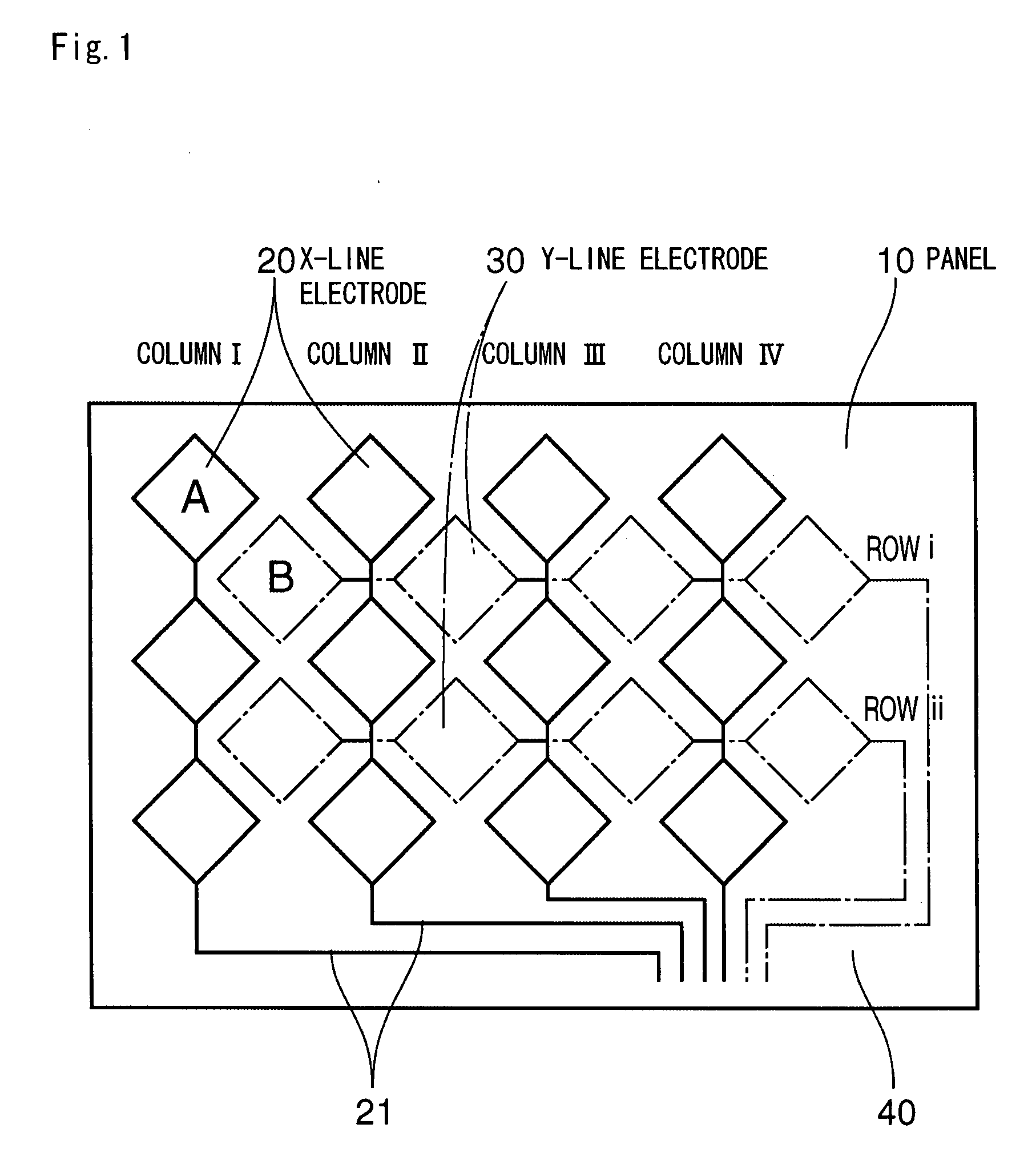
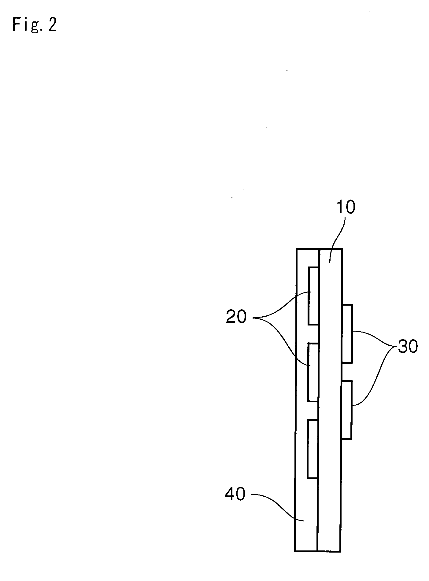
[0016] The touch panel input device described herein is a transparent touch sensor of electrostatic capacitance type used for a flexible display panel equipment. The device comprises a panel 10, X-line electrodes 20 (first electrodes), arranged on a front surface of the panel 10, and Y-line electrodes 30 (second electrodes), arranged on a back surface of the panel 10 and shifted in planer position relative to the first electrode. The device can detect whether or not a finger has touched vicinities of certain zones between X-line electrodes 20 and Y-line electrodes 30 on the front surface of the panel 10.

[0017] The panel 10 is configured with a base material having optical transparency and flexibility so as to be transparent and bendable along a linearly curved surface. Specifically, instead of laminating a plurality of transparent plates as in the conven...


PUM


Abstract

A touch panel input device of the invention has a panel, an X-line electrode (first electrodes) arranged on a front surface side of the panel, a Y-line electrode (second electrodes) disposed on the back surface side and shifted in planar position relative to the X-line electrode. The device detects whether or not a finger has touched the vicinity of a zone between the X-line electrode 20 and the Y-line electrode on the front surface of the panel. An electrostatic capacitance of the X-line electrode and an electrostatic capacitance of the Y-line electrode are made equal by way of increasing the area of the Y-line electrode with respect to that of the X-line electrode or by way of selecting an appropriate material and / or thickness of the panel and / or the coat.

Description

[0001] The present application claims priority under 35 U.S.C. §119 of Japanese Patent Application No. 2006-277,808 filed on Oct. 11, 2006, the disclosure of which is expressly incorporated by reference herein in its entity. BACKGROUND OF THE INVENTION [0002] 1. Field of the Invention [0003] The present invention relates to a touch panel input device of electrostatic capacitance type for detecting whether or not a finger has touched a predetermined position on a front surface of a panel. [0004] 2. Description of the Related Art [0005] Conventionally, this type of touch panel input device is often used with a panel overlaying glass, PEN (polyethylene naphthalate) and the like. The input device has a basic configuration in which X-line electrodes and Y-line electrodes are disposed to the front surface side and the back surface side, respectively, inside the panel and shifted in planer position relative to each other. The device is used to detect whether or not fingers have touched the...

Claims


Application Information

Patent Timeline
IPC IPC(8): G06F3/045
CPCG06F3/044G06F3/0446G06F3/0445G06F2203/04102G06F3/0448
Inventor SHIGENO, YASUHIROTAKEHARA, NAOYANAKAGAWA, HIROSHI
Owner HOSIDEN CORP
Learn More