
Inkjet printhead apparatus and method thereof

a technology of printhead and nozzle layer, applied in the direction of printing, etc., can solve the problems of increasing the possibility of damage, and deformation of the nozzle layer b>

Inactive Publication Date: 2008-05-01
SAMSUNG ELECTRONICS CO LTD
View PDF5 Cites 10 Cited by
  • Summary
  • Abstract
  • Description
  • Claims
  • Application Information

AI Technical Summary

Benefits of technology

[0011]The present general inventive concept provides a thermal inkjet printhead with a robust and reliable structure.
[0012]The present general inventive concept also provides a method of fabricating a thermal inkjet printhead with a robust and reliable structure.
[0026]A passivation layer may be formed on the heaters and the electrodes to protect the heaters and the electrodes.
[0027]An anti-cavitation layer may be formed on the passivation layer to protect the heaters from cavitation forces generated when the bubbles collapse.
[0034]The support wall may bridge a gap created by the ink feed hole to allow a transfer of mechanical force between layers that are separated by the ink feed hole and face each other.
[0045]The support wall may bridge a gap created by the ink feed hole to allow a transfer of mechanical force between the ink chamber layers that are separated by the ink feed hole and face each other.

Problems solved by technology

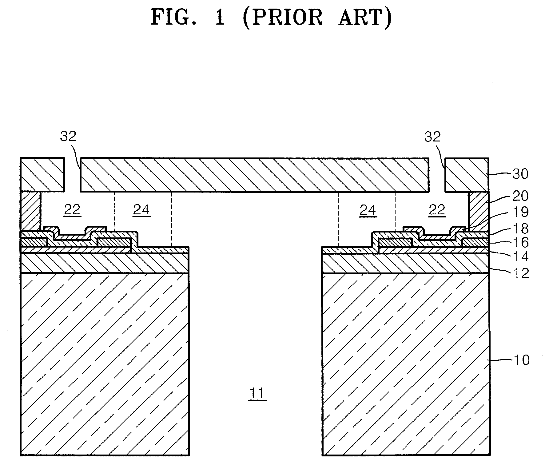
However, during manufacturing of the above inkjet printhead, a process of stacking the layers generates residual stress and a process of coupling the inkjet printhead with an ink cartridge generates thermal stress, which results in deformation of the nozzle layer 30.
As the length of the inkjet printhead increases, the possibility of damage increases.
Thus, the possibility of damage is even more likely in the line printing type inkjet printers that have been developed to realize high-speed printing.

Method used


Image

  • Inkjet printhead apparatus and method thereof
  • Inkjet printhead apparatus and method thereof
  • Inkjet printhead apparatus and method thereof

Examples


Embodiment Construction

[0054]Reference will now be made in detail to the embodiments of the present general inventive concept, examples of which are illustrated in the accompanying drawings, wherein like reference numerals refer to the like elements throughout. The embodiments are described below in order to explain the present general inventive concept by referring to the figures.

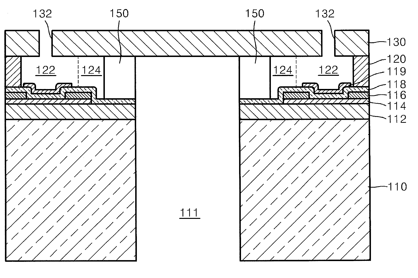
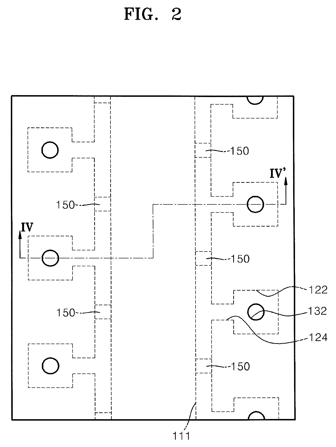
[0055]FIG. 2 is a schematic plan view of an inkjet printhead according to an embodiment of the present general inventive concept. FIG. 3 is a schematic exploded perspective view of the inkjet printhead of FIG. 2, according to an embodiment of the present general inventive concept. FIG. 4 is a sectional view taken along line IV-IV′ of FIG. 2, according to an embodiment of the present general inventive concept.

[0056]Referring to FIGS. 2 through 4, the inkjet printhead includes a substrate 110 on which a plurality of material layers are formed, including a chamber layer 120 formed above the substrate 110, a nozzle layer 130 formed ...


PUM


Abstract

An inkjet printhead including a substrate through which an ink feed hole is formed to supply ink, a chamber layer formed on the substrate and including a plurality of ink chambers which are filled with ink supplied from the ink feed hole, a nozzle layer formed on the chamber layer and including a plurality of nozzles through which ink is ejected, a plurality of support walls formed between the substrate and the nozzle layer to support the substrate and the nozzle layer, and a method of fabricating the same.

Description

CROSS-REFERENCE TO RELATED APPLICATIONS[0001]This application claims the priority of Korean Patent Application No. 10-2006-0104695, filed on Oct. 26, 2006, in the Korean Intellectual Property Office, the disclosure of which is incorporated herein in its entirety by reference.BACKGROUND OF THE INVENTION[0002]1. Field of the Invention[0003]The present general inventive concept relates to an inkjet printhead and a method of fabricating the same, and more particularly, to a thermal inkjet printhead with a robust and reliable structure.[0004]2. Description of the Related Art[0005]Inkjet printers are devices used to form color images on printing mediums by firing droplets of ink from an inkjet printhead onto a desired region of a corresponding printing medium. Inkjet printers can be classified into shuttle type inkjet printers and line printing type inkjet printers. In shuttle type inkjet printers, an inkjet printhead prints an image while moving back and forth in a direction perpendicula...

Claims


Application Information

Patent Timeline
Patent Type & Authority Applications(United States)
IPC IPC(8): B41J2/14B41J2/16
CPCB41J2/1404B41J2002/14387B41J2/14145B41J2/14129B41J2/14016
Inventor KIM, SANG-HYUNPARK, SUNG-JOONLEE, BANG-WEONLEE, JIN-WOOK
Owner SAMSUNG ELECTRONICS CO LTD
Learn More