Spherical Universal Coupling

a universal and coupling technology, applied in the direction of couplings, yielding couplings, rotary machine parts, etc., can solve the problems of high cost of joints, limited rotational speed of joints, and complex and cv-joints, so as to reduce the number of replacement parts, and the effect of simple and easy assembly

Inactive Publication Date: 2008-05-01
TORVEC INC
View PDF36 Cites 62 Cited by
  • Summary
  • Abstract
  • Description
  • Claims
  • Application Information

AI Technical Summary

Benefits of technology

[0011]In one embodiment, the invention's spherical-gear CV-joints are incorporated in an automotive half-shaft along with a small plunge adaptor on the shaft end of one of the joints. In comparison with present commercial automotive half-shafts, the half-shaft disclosed herein is (a) smaller and lighter, (b) simpler and easier to assemble, (c) much less expensive to manufacture, and (d) significantly reduces the number of replacement parts to be inventoried.

Problems solved by technology

However, such universal and CV-joints are quite complex and relatively difficult to lubricate, and the design and manufacture of such joint components is widely recognized as a very specialized and esoteric art of critical importance to the worldwide automotive industry.
While this universal joint art is very well developed, the joints are expensive, including many parts that are difficult and expensive to manufacture due to large surface areas that must be ground with extreme accuracy (e.g., 0.0002″ / 0.005 mm).
Such joints are limited in regard to the rotational speeds that they can transmit and, more particularly, in regard to the size of the angles over which they can operate efficiently because of the point contact and significant amount of sliding of the balls.
Each of these joints is complex and expensive to manufacture, e.g., the Rzeppa universal joint uses six precision ground balls that run back and forth in six respective precision ground tracks, and the tri-pot universal joint uses three precision ground spherical rollers and straight ground tracks.

Method used


Image

  • Spherical Universal Coupling
  • Spherical Universal Coupling
  • Spherical Universal Coupling

Examples


Embodiment Construction

Spherical Gear System

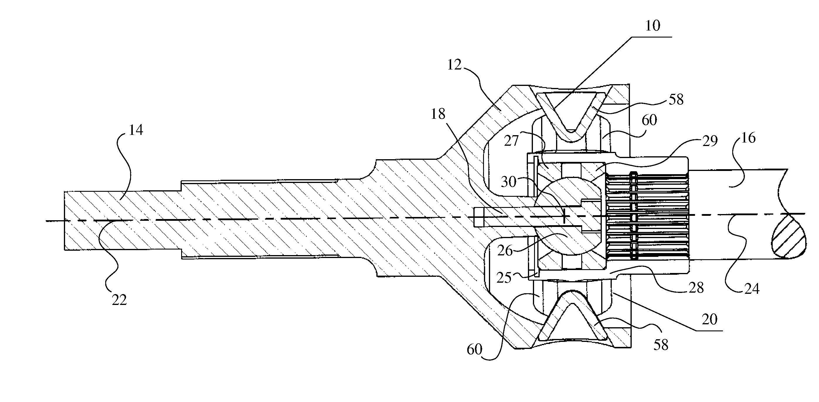
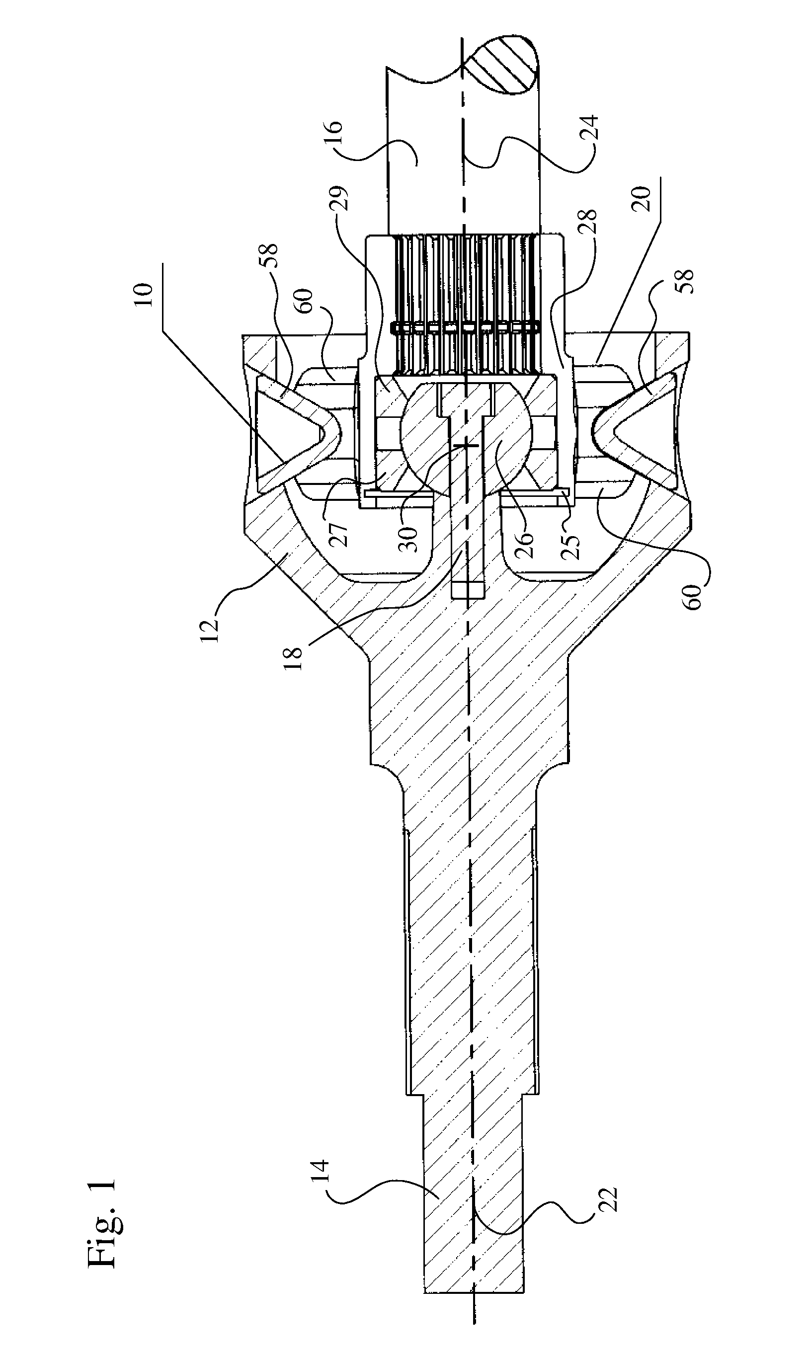
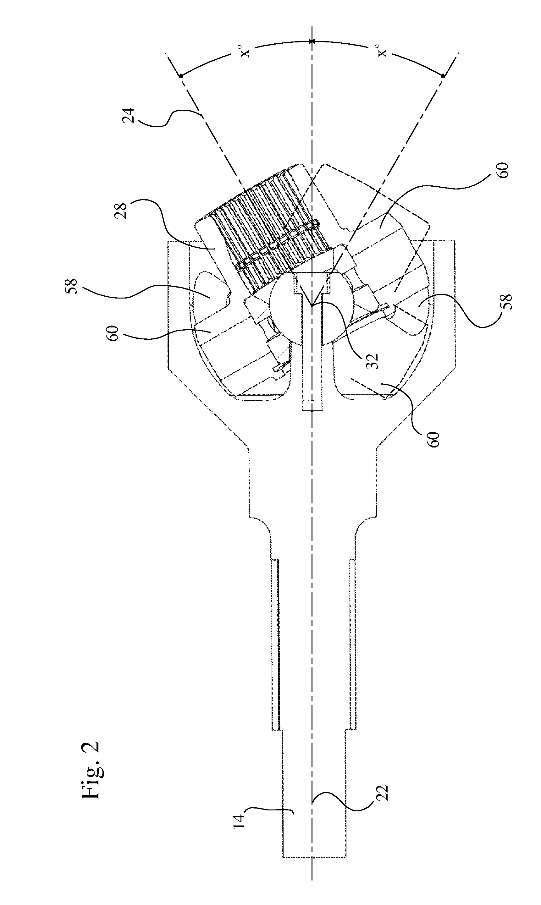
[0024]FIG. 1 and FIG. 2 illustrate a constant-velocity universal joint using spherical gears for interconnecting a pair of rotating shafts. FIG. 1 is a schematic and partially cross-sectional view of an internal gear 10 (with internal teeth 58) fixed within a cup-like support 12 having one end fixed to a first shaft 14. A mating external gear 20 (with external teeth 60) is fixed for rotation to a second shaft 16. In FIG. 1, shafts 14 and 16 are shown with their respective axes 22, 24 positioned in 180° alignment. Axes 22, 24 are also the respective axes of mating spherical gears 10, 20.

[0025]A spherical bearing maintains the mating gears 10 and 20 in proper meshing relationship. This spherical bearing includes (a) an interior member, preferably a centering ball 26, fixed to the base of cup-like support 12 by bolt 18, and (b) an exterior member in the form of a hub 28 formed on the interior of gear 20. The latter includes two spherical rings 27 and 29 that captur...


PUM


Abstract

A pair of spherical gears connects the intersecting shafts of a CV-joint. One gear has internal teeth, and the other has external teeth. The gear design is based on pitch circles that are great circles on theoretical pitch spheres that are concentric and have identical radii. The gear teeth are preferably straight-sided. Individual smaller construction spheres are arranged in a circle so that the points of tangency between successive smaller spheres are all positioned on the circumference of the identical pitch circles of the gears and are all also positioned on the respective pitch circles of each successive smaller construction sphere. The straight-sided tooth faces of the teeth of the internal gear are preferably cone shaped. The preferred embodiment uses six teeth on each gear, and the gears, while rotating at high speeds under load, can intersect throughout a continuous maximum range of 60° or more.

Description

BACKGROUND OF THE INVENTION[0001]1. Field of the Invention[0002]The invention relates to universal couplings and automotive half-shafts, and more particularly, to constant-velocity universal joints for directly connecting two shafts in a manner that transmits rotation from the driving shaft to the driven shaft while, at the same time, permitting the angle of intersection between the axes of the shafts to be varied away from 180° alignment in any direction over a relatively wide and continuous range of angles (e.g., 60° or more).[0003]2. Description of Related Art[0004]There are well known non-gear means for transmitting rotary motion between shafts experiencing angular change. Perhaps the best known of such devices are the universal joints used to connect the drive shafts and wheel axles of automotive vehicles. Such universal joints are often constructed in the venerable double-yoke (Cardan) form of two small intersecting axles interconnected by a pair of yokes. However, the shafts ...

Claims


Application Information

Patent Timeline
Patent Type & Authority Applications(United States)
IPC IPC(8): F16D3/00
CPCF16D3/185Y10S464/904F16D3/2057
Inventor GLEASMAN, KEITH E.
Owner TORVEC INC
Why Eureka
Try Eureka