
Clamping system and method for fusing vertebral elements in a spine

a technology of vertebral elements and fusion system, which is applied in the field of fusion system and method of vertebral elements in the spine, can solve the problems of reducing the incidence of fusion, degenerative disorders of the spine can produce debilitating pain, and the rod and screw system is generally not suited to minimally invasive surgical (mis) techniques

Inactive Publication Date: 2008-05-01
G&L CONSULTING
View PDF12 Cites 57 Cited by
  • Summary
  • Abstract
  • Description
  • Claims
  • Application Information

AI Technical Summary

Problems solved by technology

Traumatic, inflammatory, metabolic, and degenerative disorders of the spine can produce debilitating pain.
Because the vertical compression loads of the spine do not pass directly through the axis of the rod, rod and screw systems cannot resist these loads without considerable flexing, reducing the incidence of fusion.
Rod and screw systems are generally not suited to minimally invasive surgical (MIS) techniques because the rods span vertebral levels and must be forced through muscle tissue between the vertebrae, causing significant tissue trauma.
There are many MIS rod and screw systems, but most are unsatisfactory and some only span one level.

Method used


Image

  • Clamping system and method for fusing vertebral elements in a spine
  • Clamping system and method for fusing vertebral elements in a spine
  • Clamping system and method for fusing vertebral elements in a spine

Examples


Embodiment Construction

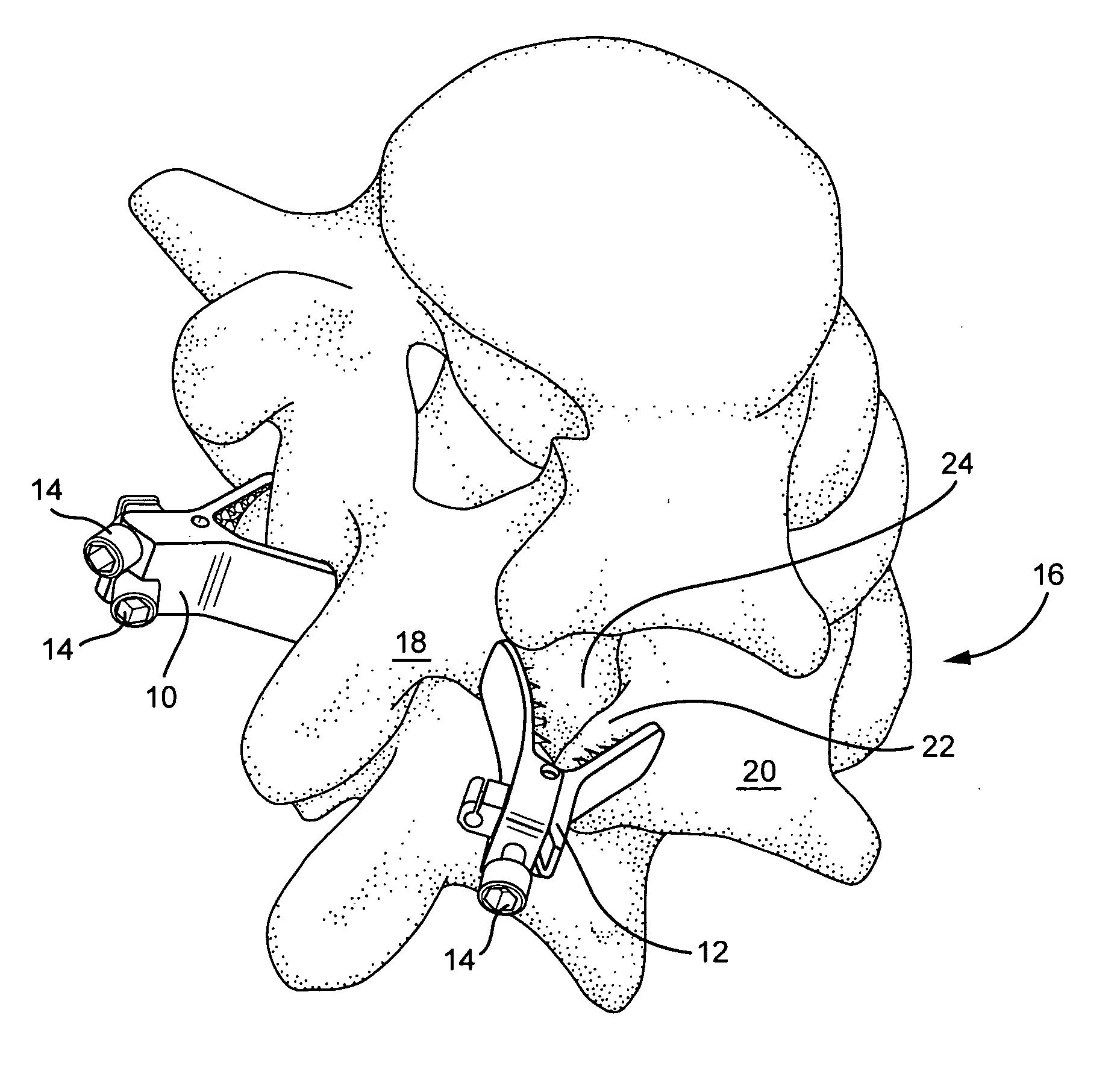
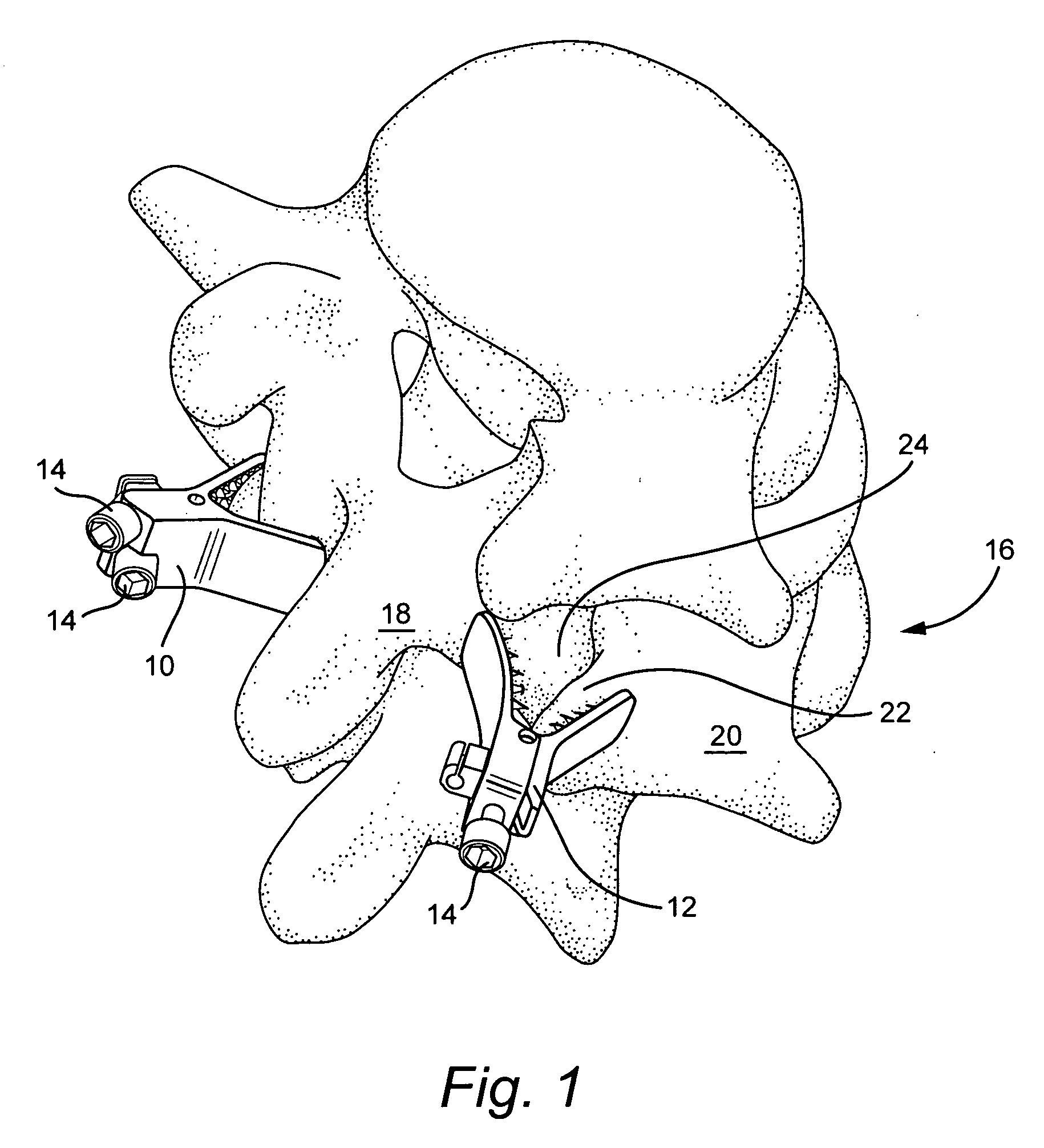
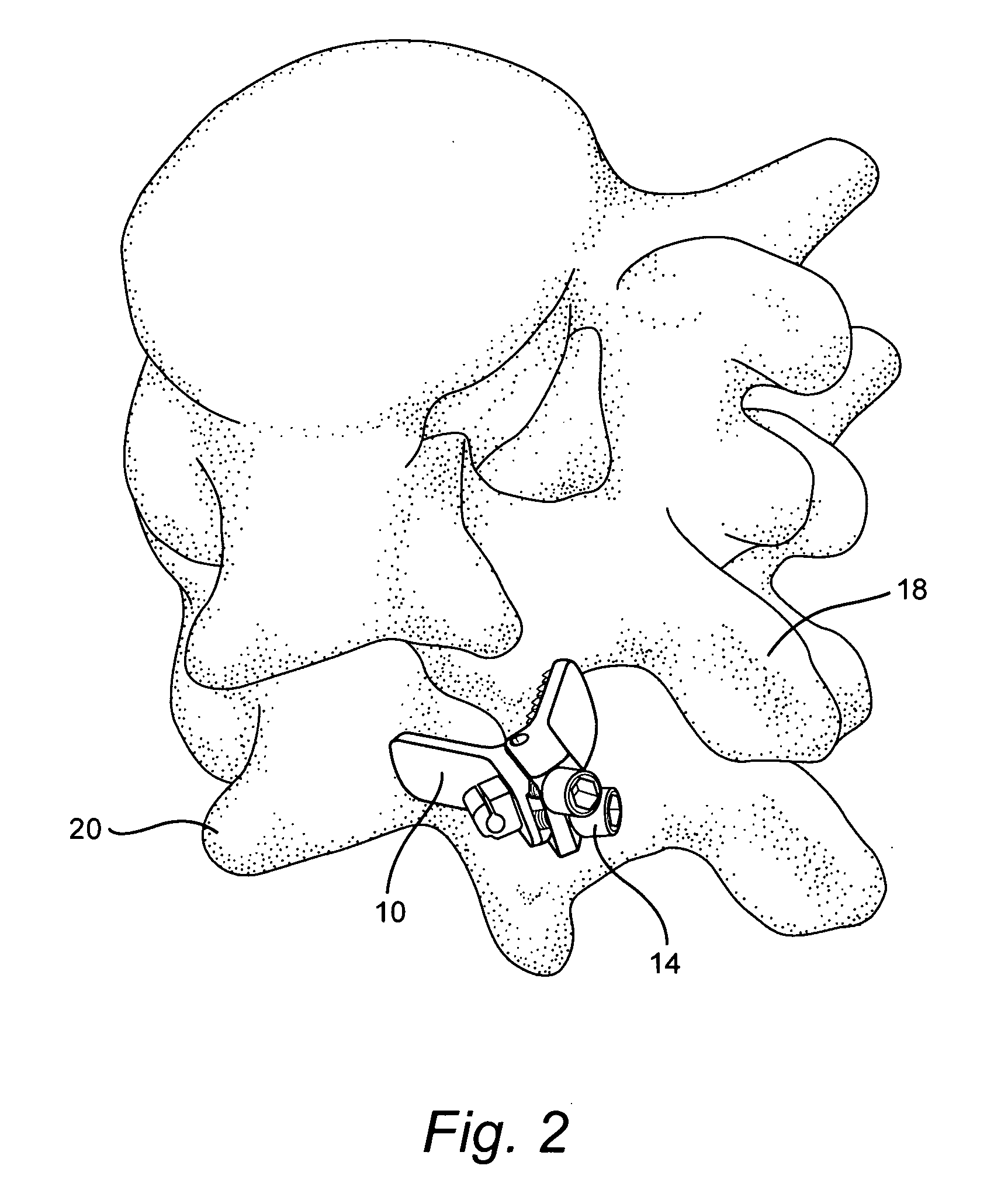
[0018]FIG. 1 shows a pair of facet joint clamps 10, 12 attached to the spine to fix bones being fused. Similarly, FIG. 2 shows a facet joint clamp attached to the spin to fix bones being fused.

[0019] The jaws of the clamps pivot under the control of adjustment screws 14. The clamps may be surgically inserted into a patient and to the spine 16 with the jaws held wide-open. The clamps 10 when applied to the spine may hold together adjacent upper and lower vertebra 18, 20. For example, the clamps may grasp opposing facet joint bones 22, 24.

[0020] The surgeon steers the clamps 10 to the spine and seats the clamp on the spine with a steering device. The jaws may be seated such that they are adjacent outer surfaces of opposing facet joint bones 22, 24. Once the clamp is properly seated, the surgeon closes the jaws of the clamp by turning the adjustment screws 14. The screw force the jaws to close and securely grasp the bones of the spine. The number of turns applied to the adjustment sc...


PUM


Abstract

A facet joint clamp to fix spine facet joints in a spine of a mammalian patent, the clamp including: a first plate and second plate each including a jaw section and a base, wherein the base is at an acute angle with respect to the jaw section, and the jaw section has an inside surface adapted to grasp the spine; a hinge in the base section of the first and second plates and forming a pivot joint between the plates and an adjustment mechanism to controllably pivot the first plate with respect to the second plate.

Description

BACKGROUND OF THE INVENTION [0001] This application claims the benefit of U.S. Provisional Patent Application Ser. No. 60 / 862,511, filed Oct. 23, 2006, the entirety of which is incorporated by reference. [0002] The present invention relates to surgical devices and methods to clamp a spinal facet joint and instruments for steering and applying clamps to the spinal facet joint. [0003] Traumatic, inflammatory, metabolic, and degenerative disorders of the spine can produce debilitating pain. A common surgical interventions today is arthrodesis, e.g., spinal fusion. Spinal fusion surgery generally requires a surgeon to access the spine and apply treatment devices, e.g., screws, rods, bone grafts and artificial discs, that effectively fuse adjacent vertebra. [0004] A traditional surgical approach to the spine is through the back of a patient. The surgeon cuts a mid-line incision in the back that is approximately three inches to six inches long to access the spine. A bone graft is obtained...

Claims


Application Information

Patent Timeline
IPC IPC(8): A61B17/08A61B17/58
CPCA61B17/7064
Inventor GATELY, NICHOLAS
Owner G&L CONSULTING
Learn More