Front fork

Inactive Publication Date: 2008-05-08
KYB CORP
View PDF6 Cites 4 Cited by
  • Summary
  • Abstract
  • Description
  • Claims
  • Application Information

AI Technical Summary

Benefits of technology

[0007] This invention has been designed in consideration of this problem, and it is an object thereof to provide a front fork that can improve riding comfort when a fork main body begins a contraction operation from a state of maximum expansion.

Problems solved by technology

Hence, the damper does not perform a contraction operation when the fork main body begins the contraction operation from the state of maximum expansion, and consequently the front fork takes a so-called rod form and does not begin the contraction operation smoothly.

Method used


Image

  • Front fork
  • Front fork

Examples


Embodiment Construction

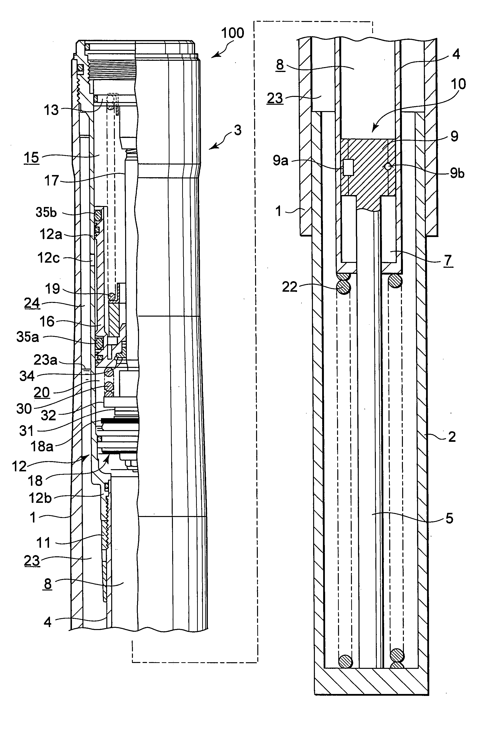
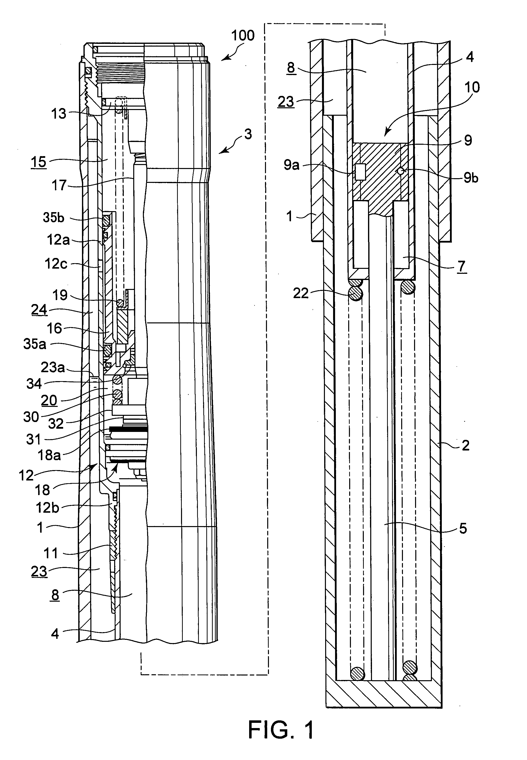
[0010] Referring to FIG. 1, a front fork 100 according to an embodiment of this invention will be described. In FIG. 1, a lower portion side of the front fork 100 shows an outline.

[0011] The front fork 100 is interposed between a vehicle body and a wheel of a two-wheeled vehicle, more particularly on a front wheel side of a motorcycle, and functions as a hydraulic shock absorber that absorbs road surface vibration input into the front wheel to suppress variation in the attitude of the vehicle body.

[0012] The front fork 100 takes an inverted shape in which a wheel side tube 2 serving as an inner tube is inserted slidably in a vehicle body side tube 1 serving as an outer tube. The vehicle body side tube 1 and wheel side tube 2 constitute a fork main body 3 that can expand and contract freely.

[0013] A damper 10 that generates a predetermined damping force as the fork main body 3 expands and contracts is disposed in an axial core portion of the fork main body 3. The damper 10 compris...


PUM


Abstract

The front fork (100) includes a fork main body (3) in which an inner tube (2) is inserted into an outer tube (1) to enable free expansion and contraction, a damper (10) generates a damping force when a rod (5) moves within a cylinder (4) as the fork main body (3) expands and contracts, an air chamber (15) delimited by a free piston (16), which compensates for variation in the internal volume of the cylinder (4) caused by invasion and retreat of the rod (5) into and from the cylinder (4), a pressurizing spring (19) housed in the air chamber (15), which biases the free piston (16) in a direction for enlarging the air chamber (15), and a sub-spring (30) which biases the free piston (16) in a direction for shrinking the air chamber (15) in opposition to the pressurizing spring (19).

Description

TECHNICAL FIELD OF THE INVENTION [0001] This invention relates to a front fork and, particularly, to a front fork mounted at a front wheel end of a two-wheeled vehicle to function as a hydraulic shock absorber. DESCRIPTION OF RELATED ART [0002] As a front fork that is interposed on a front wheel side of a two-wheeled vehicle to absorb road surface vibration input into the front wheel, JP2005-30534 discloses a front fork in which a damper is provided in an axial core portion of a fork main body constituted by a handlebar side tube and a wheel side tube such that a damping force is exhibited by the damper when the fork main body expands and contracts. [0003] In the front fork disclosed in JP2005-30534, a cylinder body is connected to the vehicle body side tube and a rod body is connected to the wheel side tube. A base valve and a free piston are disposed in a rod-opposing side oil chamber of a cylinder body, and the free piston is biased from behind by a pressurizing spring. [0004] Th...

Claims


Application Information

Patent Timeline
IPC IPC(8): B62K25/04
CPCF16F9/062B62K25/08
Inventor FURUYA, KEN
Owner KYB CORP
Why Eureka
Try Eureka