
Control device for vehicle

Inactive Publication Date: 2019-12-19
HONDA MOTOR CO LTD
View PDF0 Cites 5 Cited by
  • Summary
  • Abstract
  • Description
  • Claims
  • Application Information

AI Technical Summary

Benefits of technology

The disclosure provides a control device for a vehicle that can select a shift stage that puts occupant comfort first, in the control of acceleration and deceleration under automatic driving control. This device can effectively improve the ride comfort of the vehicle by reducing the occurrence of shift shock and by allowing the vehicle to change lane or accelerate at requested acceleration, while also ensuring traveling performance. The device can properly acquire external information of the vehicle by using an imaging device, radar detection, or inter-vehicle communication, and limiting the engine rotation speed can prevent an excessive rise of the engine rotation speed (blow-up) and deceleration. Overall, the control device described in this patent text makes it easy to select a shift stage that puts occupant comfort first, and enhances the overall comfort and performance of the vehicle.

Problems solved by technology

However, in the case where the shift stage is selected based on the vehicle speed feedback or the accelerator pedal opening degree, particularly when the vehicle is going to change the lane, the shift stage that gives priority to reaching the requested acceleration is selected, so a shock (vibration and noise) may be generated as the shift stage is switched, and it may affect the comfort (ride comfort) of the occupant of the vehicle.

Method used


Image

  • Control device for vehicle
  • Control device for vehicle
  • Control device for vehicle

Examples


Embodiment Construction

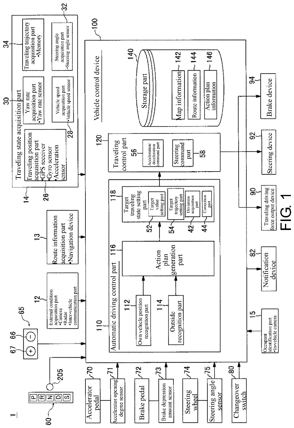
[0023]Embodiments of the disclosure will be described below with reference to the accompanying drawings. FIG. 1 is a functional configuration diagram of a control device 100 mounted on a vehicle 1. A configuration of the control device 100 will be described with reference to FIG. 1. The vehicle (own vehicle) 1 on which the control device 100 is mounted is a two-wheeled, three-wheeled, or four-wheeled automobile, for example, and includes an automobile powered by an internal combustion engine such as a diesel engine or a gasoline engine, an electric automobile powered by an electric motor, a hybrid automobile having both an internal combustion engine and an electric motor, and the like. Further, the above-mentioned electric automobile is driven using electric power discharged by a battery such as a secondary battery, a hydrogen fuel cell, a metal fuel cell, and an alcohol fuel cell.

[0024]The control device 100 includes part for taking in various types of information from the outside ...


PUM


Abstract

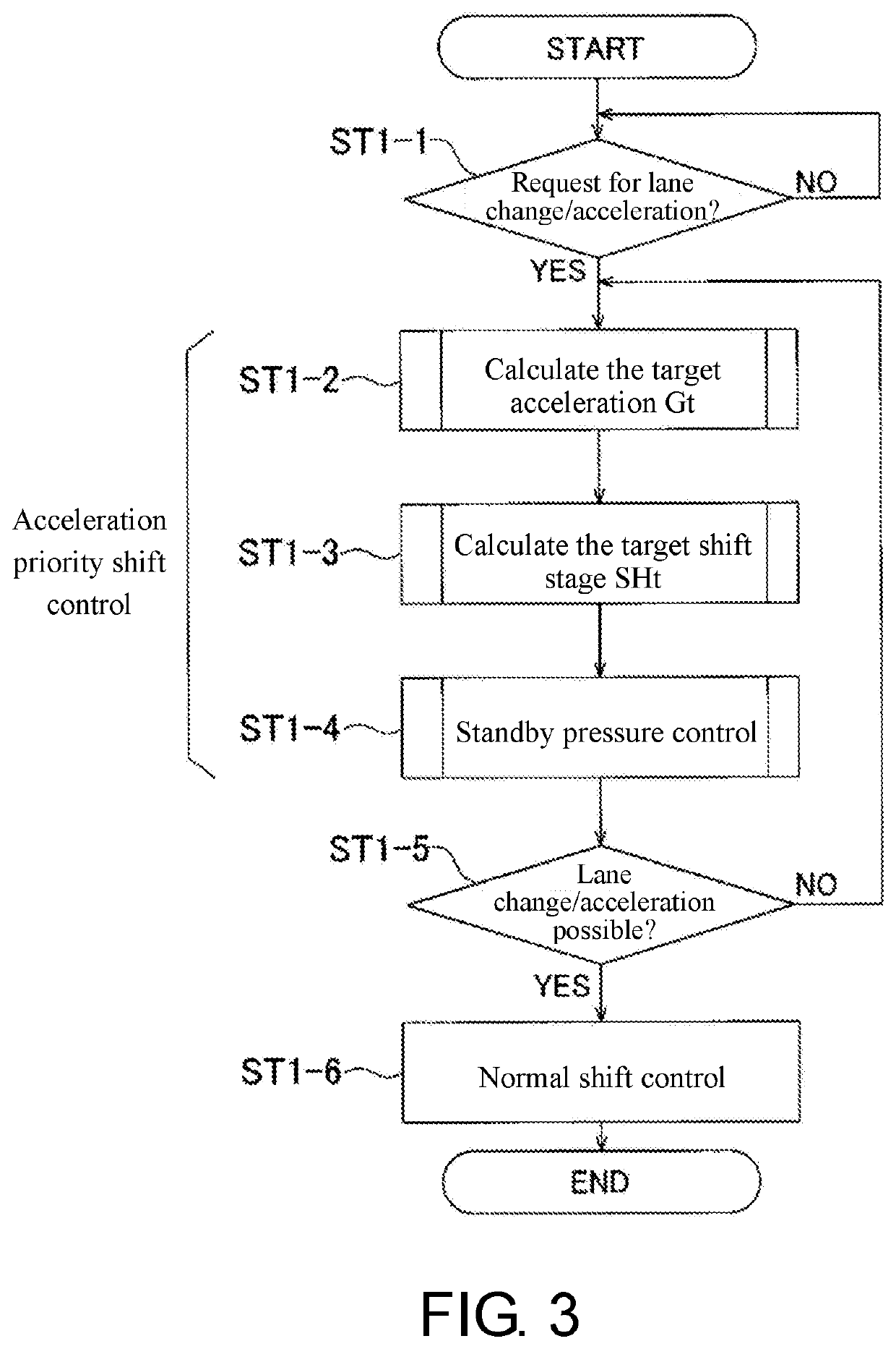
The disclosure provides a control device for a vehicle, as an acceleration priority shift control that selects the shift stage set by the automatic transmission (TM) by preferentially using the information of acceleration of the vehicle (1), the traveling control part (120) calculates a maximum acceleration (Gmax) and a minimum acceleration (Gmin) of the vehicle (1) by using external information of the vehicle (1); calculates a target acceleration (Gt) by comparing the calculated maximum acceleration (Gmax) and minimum acceleration (Gmin) with a preset optimum acceleration (Gi); calculates a target shift stage (SHt) of the automatic transmission (TM) based on a current state of an engine (EG) in accordance with the calculated target acceleration (Gt); and calculates a standby pressure (Pm) for a clutch of the calculated target shift stage (SHt), and performs standby pressure control of the clutch with the calculated standby pressure (Pm).

Description

CROSS-REFERENCE TO RELATED APPLICATION[0001]This application claims the priority benefit of Japan application serial no. 2018-114019, filed on Jun. 14, 2018. The entirety of the above-mentioned patent application is hereby incorporated by reference herein and made a part of this specification.BACKGROUNDTechnical Field[0002]The disclosure relates to a control device for a vehicle, and particularly relates to a control device for a vehicle, which performs automatic driving control to automatically control at least one of acceleration, deceleration, and steering of the own vehicle.Description of Related Art[0003]As disclosed in Patent Document 1, for example, there is a conventional control device for a vehicle, which includes an automatic driving control part that automatically controls at least one of acceleration, deceleration, and steering of the own vehicle for the own vehicle to travel along a route to the destination. In addition, among vehicles equipped with such an automatic d...

Claims


Application Information

Patent Timeline
IPC IPC(8): B60W30/182B60W10/04B60W50/08B60W30/09
CPCB60W10/20B60W2420/42B60W2420/52B60W30/09B60W2720/106B60W50/087B60W30/182B60W10/18B60W10/04F16H61/0437F16H61/061F16H2061/062F16H61/0213F16H2061/022F16H2306/18B60W2420/403B60W2420/408
Inventor NIU, CHAOADACHI, TAKASHIMIYATA, KAZUNORI
Owner HONDA MOTOR CO LTD
Learn More