
Collapsible Mobile Radio Device

Inactive Publication Date: 2008-05-08
PANASONIC CORP
View PDF5 Cites 26 Cited by
  • Summary
  • Abstract
  • Description
  • Claims
  • Application Information

AI Technical Summary

Benefits of technology

[0008]However, in a structure that has the internal antenna disposed at the location most spaced apart from the flexible antenna attached to the outside of the casing, a spatial diversity effect with the antenna attached to the outside of the casing is obtained. However, according to this structure, there is a problem in that the performance as the internal antenna is lowered.

Problems solved by technology

However, in all of the cases, it has been known that antenna performance is much affected by a ground structure near the antenna and an adjacent metal conductor.
However, even in this case, it has been known that a positional relationship between the ground wiring line and a proximity object affects the performance of the antenna.

Method used


Image

  • Collapsible Mobile Radio Device
  • Collapsible Mobile Radio Device
  • Collapsible Mobile Radio Device

Examples


first embodiment

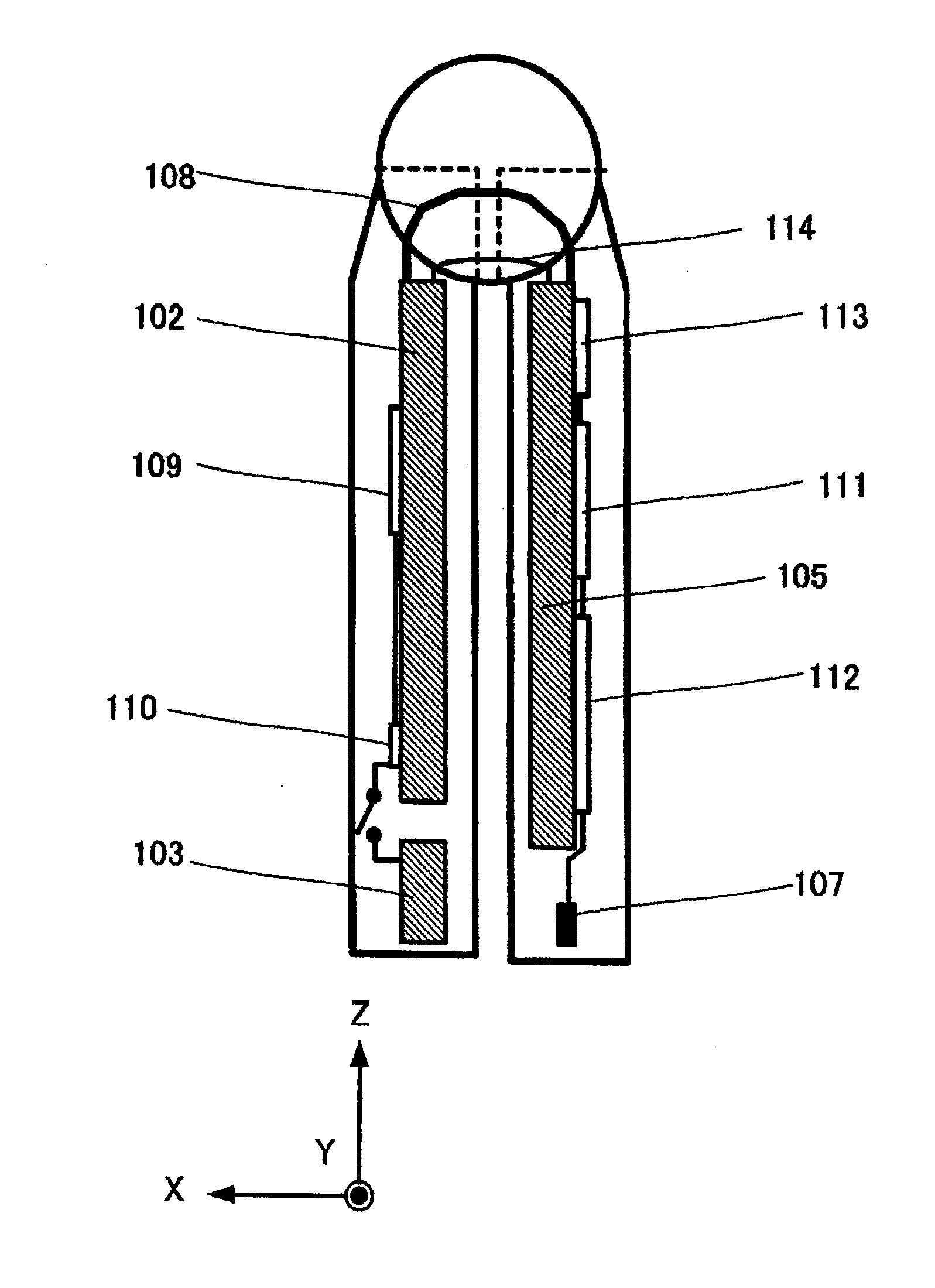
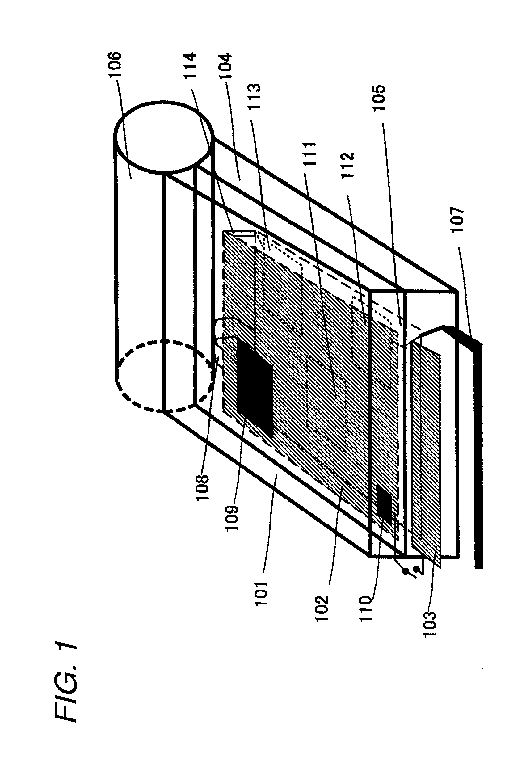
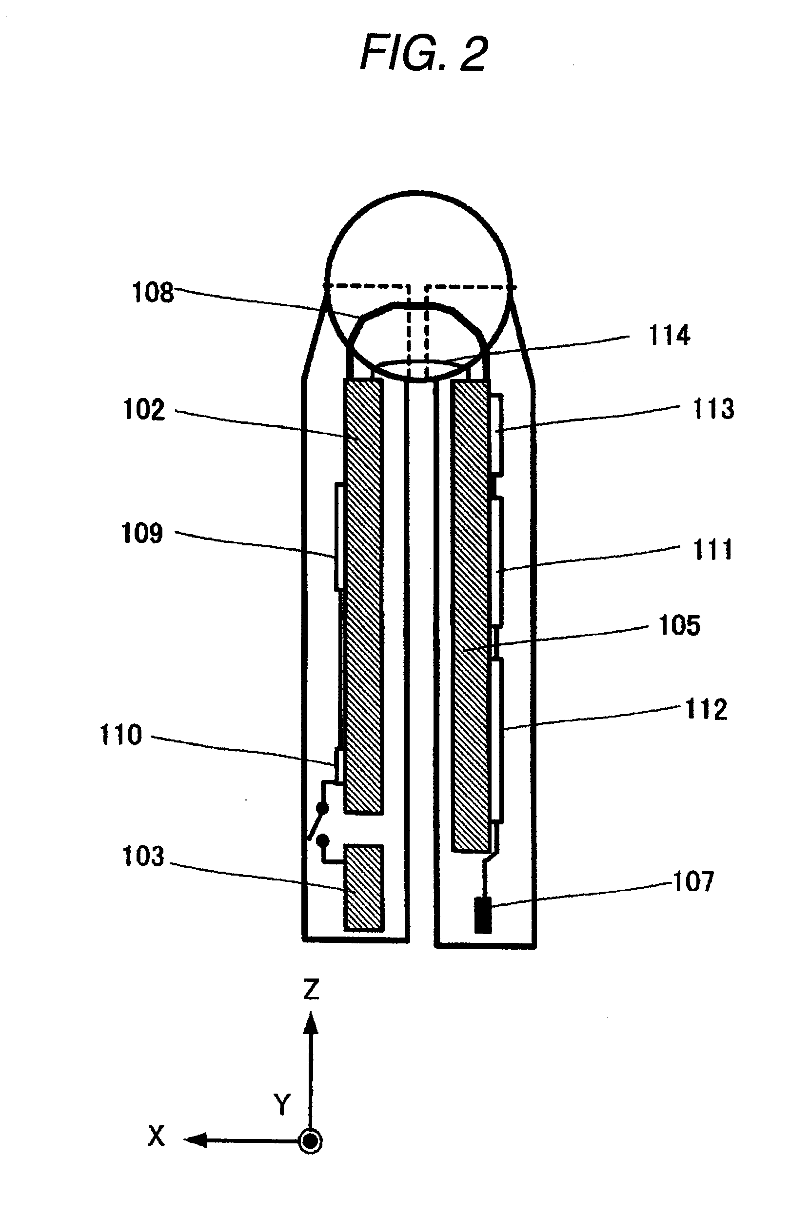
[0078]A foldable portable radio apparatus according to a first embodiment will be described with reference to FIGS. 1 to 7.

[0079]FIG. 1 is a perspective view illustrating a closed state of a foldable portable radio apparatus according to first embodiment. In FIG. 1, an upper casing 101 of the foldable portable radio apparatus is formed of a resin that has, for example a thickness of approximately 1 mm. This size is set to the longitudinal 100 mm and the horizontal 50 mm. The upper casing 101 of the foldable portable radio apparatus includes a first conductor plate 102 and a second conductor plate 103 that are provided therein. The first conductor plate 102 is composed of a printed circuit board that has, for example, a thickness of 1 mm, and the size is set to the longitudinal 70 mm and the horizontal 40 mm. A ground pattern is formed on the first conductor plate 102.

[0080]The second conductor plate 103 is composed of a printed circuit board that has, for example, a thickness of 1 m...

second embodiment

[0106]The foldable portable radio apparatus according to the second embodiment will be described with reference to FIGS. 8, 9, and 10. FIG. 8 shows a perspective view of a foldable portable radio apparatus according to a second embodiment. In FIG. 8, the same reference numerals as those of FIG. 1 perform the same operations, and the description thereof will be omitted.

[0107]The foldable portable radio apparatus according to the second embodiment shown in FIG. 8 has a structure in which in addition to the structure of the first embodiment shown in FIG. 1, a second circuit board 202, and a second switching unit 201 that electrically opens or short circuits the circuit board 105 and the second circuit board 202 according to the detected result of the detecting unit 109 are additionally provided.

[0108]FIG. 9 shows a side view of a foldable portable radio apparatus according to a second embodiment. In FIG. 9, the same reference numerals as those of FIG. 1 perform the same operations, and...

third embodiment

[0115]The foldable portable radio apparatus according to the third embodiment will be described with reference to FIGS. 11 and 12. FIG. 11 shows a perspective view of a foldable portable radio apparatus according to the third embodiment. In FIG. 11, the same reference numerals as those of FIG. 8 perform the same operations, and the description thereof will be omitted.

[0116]The foldable portable radio apparatus according to the third embodiment shown in FIG. 11 has a structure in which in addition to the structure of the second embodiment shown in FIG. 8, a first reactance unit 301 and a second reactance unit 302 are additionally provided.

[0117]In the foldable portable radio apparatus according to the third embodiment, the first switching unit 110 and the second switching unit 201 operate through the first reactance unit 301 and the second reactance unit 302, respectively.

[0118]In this case, a state where the first antenna is selected and the first reactance unit 301 and the second r...


PUM


Abstract

The invention is to improve antenna performance in an internal antenna in a closed state without deteriorating the antenna performance in a state where a foldable portable radio apparatus is opened. A foldable portable radio apparatus includes a foldable mechanism in which an upper casing 101 and a lower casing 104 are rotatably connected, a first conductor plate 102 and a second conductor plate 103 that are provided in the upper casing 101, and a feeding system that is provided in the lower casing 104, and connects an antenna element 107, a circuit board 105, the first conductor plate 102, and the circuit board, a detecting unit 109 that detects opened and closed states between the upper casing 101 and the lower casing 104, and a first switching unit 110 that switches between an electrically opened state and an electrically short-circuited state between the first conductor plate and the second conductor plate according to the detected result by the detecting unit 109.

Description

TECHNICAL FIELD[0001]The present invention relates to a portable radio apparatus that includes a foldable mechanism, and more particularly, to an antenna that is incorporated into a casing and a ground structure in upper and lower casings.BACKGROUND ART[0002]In recent times, an antenna that is incorporated into a foldable cellular phone is mainly disposed like a case where the antenna is disposed on a lower end of a lower casing and a case where the antenna is disposed in an upper casing. However, in all of the cases, it has been known that antenna performance is much affected by a ground structure near the antenna and an adjacent metal conductor.[0003]Further, as a size of a cellular phone is decreased, a length of a casing is decreased, and thus an antenna bandwidth is reduced. According to this trend, a structure has been suggested in which a ground wiring line is disposed near a feeding point of the antenna. However, even in this case, it has been known that a positional relatio...

Claims


Application Information

Patent Timeline
IPC IPC(8): H01Q1/24
CPCH04M1/0245H01Q1/243H01Q1/48H04M1/0214H01Q19/005H01Q21/28H01Q9/0442
Inventor MASHIMA, NOBUHARUNAKANISHI, KIYOSHIHIRAI, MASAYOSHINAKANISHI, HIDEO
Owner PANASONIC CORP
Learn More