Body Frame and Vehicle

Inactive Publication Date: 2008-05-15
YAMAHA MOTOR CO LTD
View PDF27 Cites 21 Cited by
  • Summary
  • Abstract
  • Description
  • Claims
  • Application Information

AI Technical Summary

Benefits of technology

[0016]In another embodiment, another end of the second frame is connected to an upper portion of the head pipe. The second frame can thereby be a spring element and can be changed in accordance with the vehicle. In this case, when the second frame is formed by forging, the cross-sectional shape of the second frame can be changed inexpensively and easily.
[0017]In another embodiment, another end of the second frame is connected to a lower portion of the head pipe. This reinforces the relation between the first frame and the lower part of the head pipe and improves the rigidity of the first frame.
[0018]In another embodiment, at least one of the head pipe and the first frame has a C-shaped cross section. This improves flexibility in the shape of the head pipe and the first frame, thereby allowing easy manufacture by die casting, forging or the like.
[0019]In another embodiment, the first frame comprises a pair of frames that extend rearward with a predetermined spacing therebetween and approach each other toward the head pipe. The pair of frames can thereby be arranged in a V-shape or a U-shape and intersect each other at a predetermined angle to the head pipe, thereby increasing the horizontal rigidity of the body frame.
[0020]In another embodimen

Problems solved by technology

This structure is disadvantageous in that the

Method used


Image

  • Body Frame and Vehicle
  • Body Frame and Vehicle
  • Body Frame and Vehicle

Examples


first embodiment

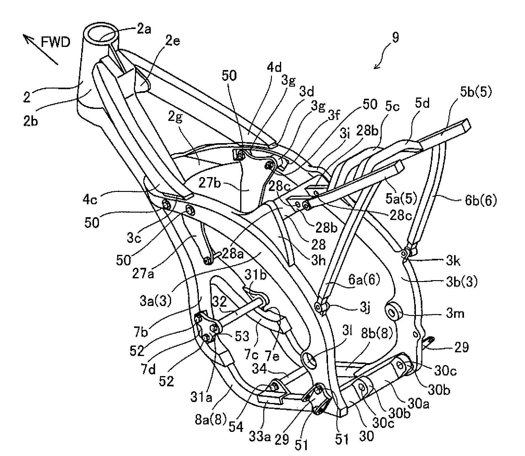
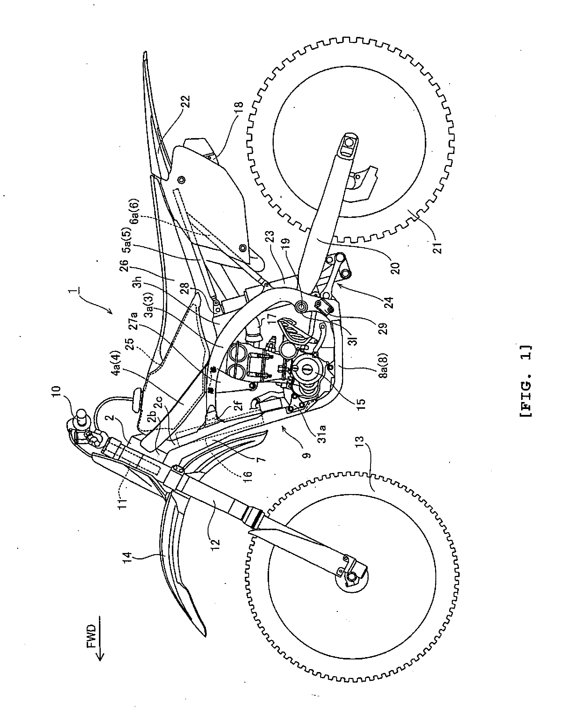
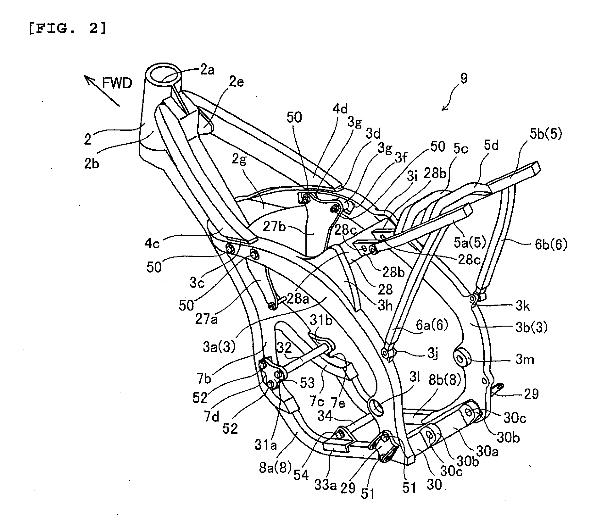
[0040]FIG. 1 is a side view of a motorcycle 1 according to a first embodiment of the present invention. FIGS. 2-11 are explanatory views of a body frame of motorcycle 1. A motorcycle is merely one example of a vehicle according to the present invention. The direction indicated by the arrow FWD in the drawings is a forward traveling direction of motorcycle 1. The structure of motorcycle 1 according to the first embodiment of the invention is now described with reference to FIGS. 1-11.

[0041]Motorcycle 1 has a main frame 3 of which a front end is directly connected to a head pipe 2. Main frame 3 extends in a downwardly rearward direction. Main frame 3 is an example of the “first frame” of the present invention.

[0042]A tank rail 4 is interposed between a rear portion of head pipe 2 and an upper portion of main frame 3. More specifically, a front end (one end) of tank rail 4 is connected to the rear portion of head pipe 2, and a rear end (other end) of tank rail 4 is connected to the upp...

second embodiment

[0075]FIGS. 12 and 13 are explanatory views of a body frame of a motorcycle according to a second embodiment of the present invention. In the second embodiment, in contrast to the first embodiment, the front end of main frame 63 is connected directly to the rear section of cylindrical part 62b of head pipe 62.

[0076]As shown in FIG. 12 the front end of main frame 63 is directly connected to head pipe 62. Main frame 63 extends in a downwardly rearward direction and is an example of the “first frame” of the present invention.

[0077]Reinforcement member 64 is interposed between the rear of head pipe 62 and main frame 63. A front (one) end of reinforcement member 64 is connected to a part of head pipe 62 lower than the part where main frame 63 is connected, and a rear (other) end of reinforcement member 64 is connected to a lower part of main frame 63. Reinforcement member 64 is an example of the “second frame” of the present invention. A down tube 67 is disposed under head pipe 62. A low...


PUM


Abstract

A body frame for a vehicle such as a motorcycle with a minimized number of parts. A main frame is connected to a head pipe and supports a rear arm to which a rear wheel is attached. A tank rail is connected to the head pipe at one end and to the main frame at the other end.

Description

RELATED APPLICATIONS[0001]This application claims the benefit of priority under 35 USC 119 of Japanese patent application nos. 2006-308757, filed on Nov. 15, 2006, and 2007-272716, filed on Oct. 19, 2007, which applications are hereby incorporated by reference in their entireties.BACKGROUND OF THE INVENTION[0002]1. Field of the Invention[0003]The present invention relates to a body frame of a vehicle, and in particular to a body frame including a head pipe.[0004]2. Description of Related Art[0005]Conventionally, a body frame including a head pipe has been known. In JP-A-2001-278158, for example, a body frame is disclosed. The body frame includes a head pipe, pivot plates supporting a rear swing arm (rear arm) to which a rear wheel is attached, a main frame connecting between the head pipe and the pivot plates and supporting a fuel tank, a down tube attached to a lower portion of the head pipe, a gusset (reinforcing plate) connecting the down tube with the main frame, a tension pipe ...

Claims


Application Information

Patent Timeline
IPC IPC(8): B62K11/02
CPCB62K25/283B62K11/04
Inventor MIYASHIRO, SHIDEHIKOOKAMOTO, TOSHIO
Owner YAMAHA MOTOR CO LTD
Why Eureka
Try Eureka