Rotational Dispensing Cap Closure for a Liquid Container

a technology of liquid containers and dispensing caps, which is applied in the direction of liquid transferring devices, single-unit devices, transportation and packaging, etc., can solve the problems of disadvantaged liquid dispensing caps, contamination of container contents, and difficulty in manually adjusting the dispensing spout from the closed position in the slo

Inactive Publication Date: 2008-05-15
MEADWESTVACO CALMAR INC
View PDF2 Cites 34 Cited by
  • Summary
  • Abstract
  • Description
  • Claims
  • Application Information

AI Technical Summary

Benefits of technology

[0011]The spout is mounted in the liquid discharge passage for linear reciprocating movement between a first, closed position and a second, opened position of the spout housing relative to the cap base. The spout has an interior bore that extends completely through the spout. A valve element is positioned in the bore. The valve element includes a resiliently flexible portion that engages in sealing engagement against the interior surface of the spout bore. When subjected to liquid pressure, the flexibility of the valve element allows the valve element to move away from the interior surface of the spout bore, and allows liquid to be dispensed through the spout bore past the valve element and from the spout. When the spout is moved to the first, closed position of the spout relative to the base, the sealing surface of the base liquid discharge passage closes the interior bore of the spout. This closes the liquid flow path through the liquid dispensing cap. When the spout is moved to the second, opened position of the spout relative to the base, the sealing surface of the base liquid discharge passage is displaced from the spout bore, communicating the spout bore with the interior of the liquid container.
[0013]Thus, the liquid dispensing cap of the invention is easily manually operated to cause the spout to move between its closed and opened positions. In the closed position, the spout seals the interior of the liquid container connected to the dispensing cap. In the opened position, the spout projects from the dispensing cap, allowing the liquid to be dispensed from the liquid container through the dispensing cap while directing the dispensed liquid from the end of the spout.

Problems solved by technology

These prior art liquid dispensing caps have been found to be disadvantaged in that, in the first example, the closure or cover can be separated from the cap.
If the closure is lost and cannot be attached over the end of the spout, the liquid contents of the container cannot be sealed from the exterior environment of the container, which could lead to the contamination of the container contents.
It is often difficult to manually pivot the dispensing spout from the closed position in the slot.

Method used


Image

  • Rotational Dispensing Cap Closure for a Liquid Container
  • Rotational Dispensing Cap Closure for a Liquid Container
  • Rotational Dispensing Cap Closure for a Liquid Container

Examples


Embodiment Construction

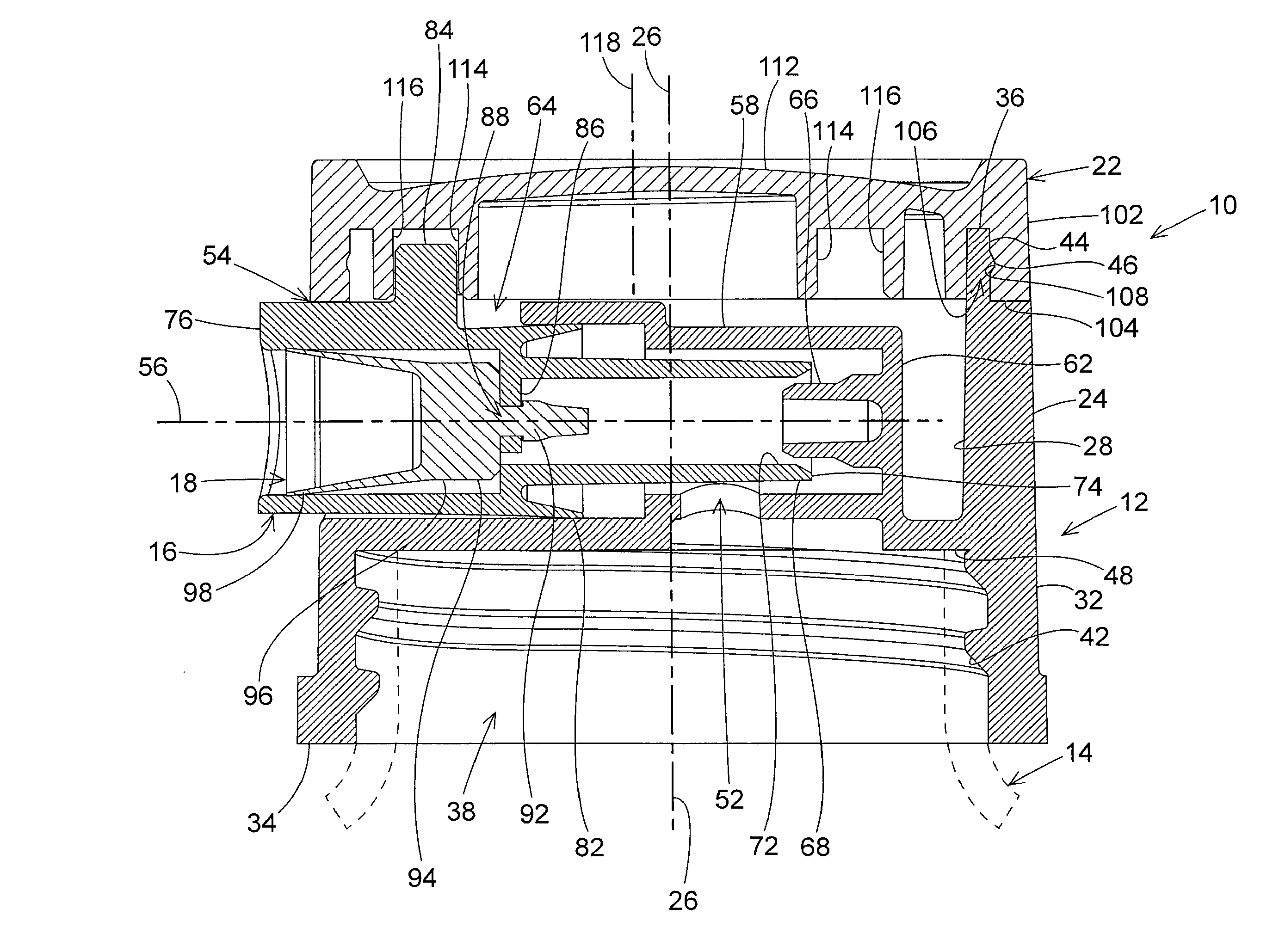
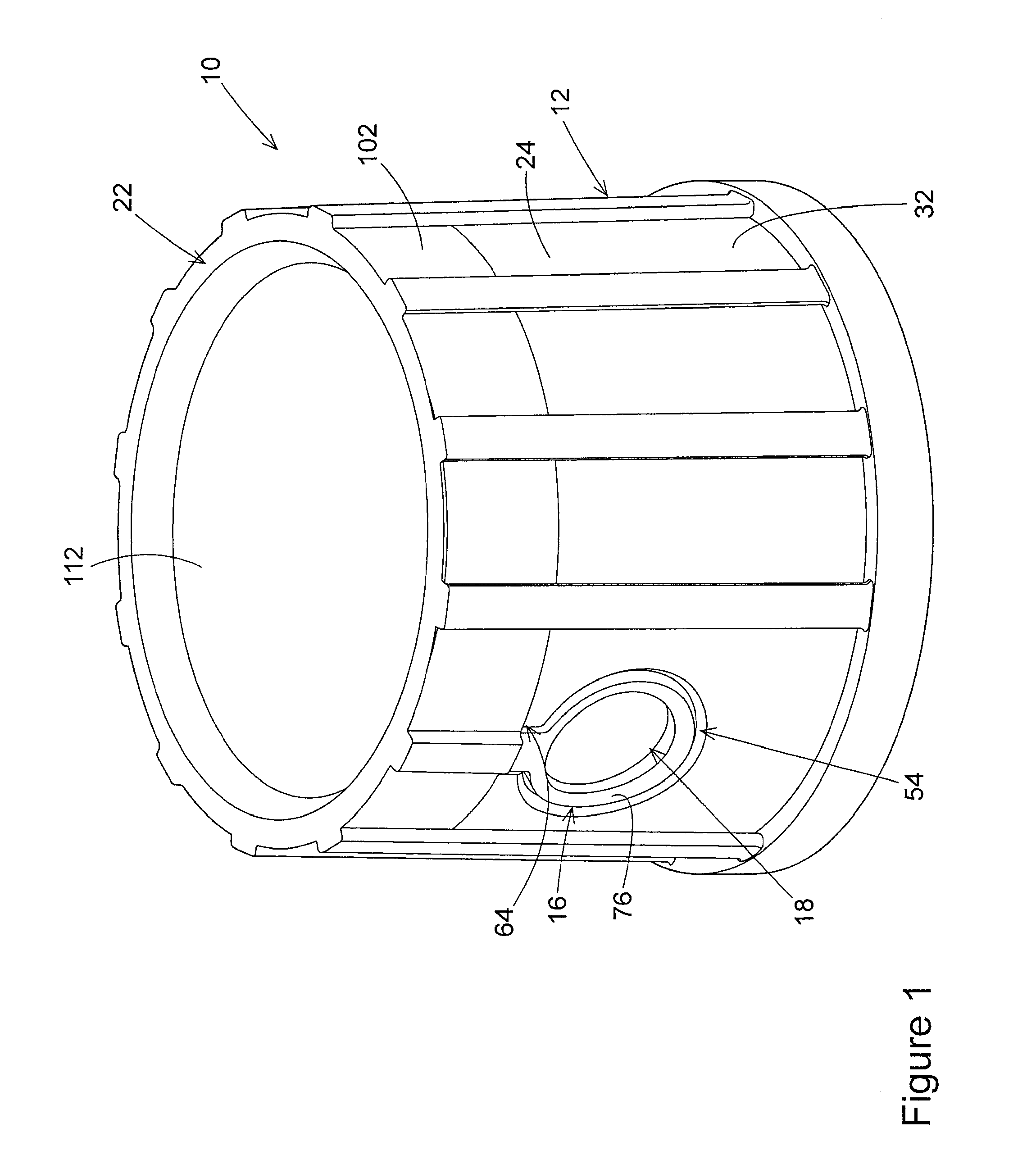
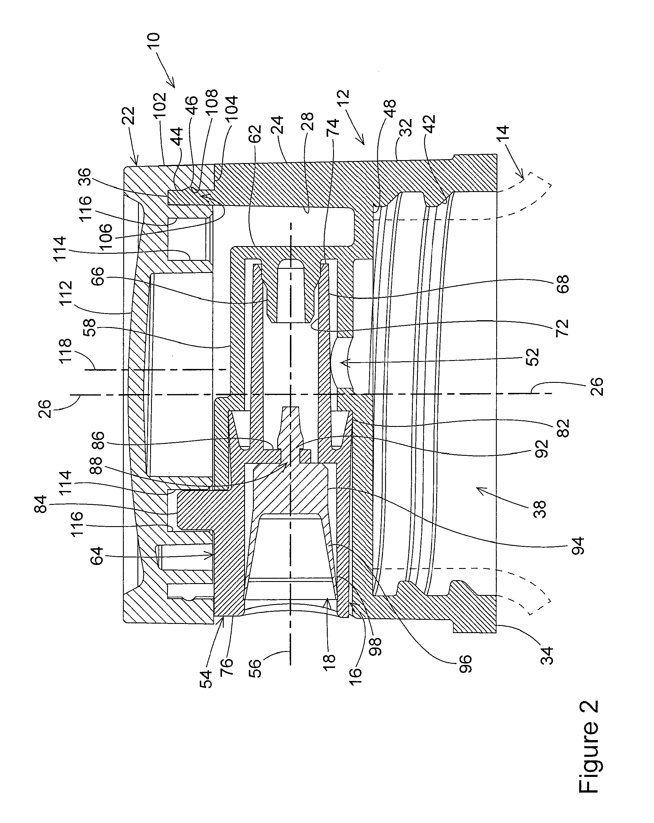
[0019]The liquid dispensing cap of the present invention is shown in FIGS. 1-4 in a closed condition of the cap and an opened condition of the cap. FIGS. 1 and 2 show the cap in the closed condition. FIGS. 3 and 4 show the cap in the opened condition. As stated earlier, the cap 10 has four basic component parts, a base 12 that is removably attachable to a liquid container 14 represented in dashed lines in FIGS. 2 and 4, a liquid dispensing spout 16 on the base 12, a valve element 18 in the spout 16, and an actuator 22 on the base 12. Each of these component parts is constructed of a plastic material conventionally used in constructing such caps. The material of the valve element is more resilient and flexible than the material of the other component parts. In the drawing figures, the dispensing cap 10 is represented as being removably attachable to the liquid container 14. This is the preferred embodiment. In alternate embodiments, the liquid dispensing cap 10 could be an integral p...


PUM


Abstract

A cap closure that dispenses liquid from a liquid container has a cylindrical base that is removably mounted on the liquid container. A valve spout is mounted on the base for linear reciprocating movement. A valve actuator is mounted on the base for rotation. The spout is movable between closed and opened positions where in the opened position liquid can be dispensed through the spout and in the closed position the liquid is blocked from passing through the spout. The actuator is operatively connected to the spout whereby rotation of the actuator between first and second positions relative to the cap base moves the spout between the respective closed and opened positions of the spout on the base.

Description

BACKGROUND OF THE INVENTION[0001](1) Field of the Invention[0002]The present invention pertains to a cap closure having a cylindrical base that is removably mounted on a liquid container. A spout is mounted on the base for linear reciprocating movement. A valve actuator is mounted on the base for rotation. The spout is movable between closed and opened positions, where in the opened position liquid can be dispensed through the spout and in the closed position the liquid is blocked from passing through the spout. The actuator is operatively connected to the spout whereby rotation of the actuator between first and second positions relative to the closure base moves the spout between the respective closed and opened positions of the spout on the base.[0003](2) Description of the Related Art[0004]A variety of different types of liquid container caps have been designed that include a liquid dispenser spout incorporated in the cap. A basic cap design includes a spout that is an integral p...

Claims


Application Information

Patent Timeline
Patent Type & Authority Applications(United States)
IPC IPC(8): B67D3/00
CPCB05B11/007B05B11/0029B65D47/244
Inventor FOSTER, DONALD D.NELSON, PHILIP L.
Owner MEADWESTVACO CALMAR INC
Why Eureka
Try Eureka