Base for Display Screen

a technology for a base and a display screen, which is applied in the direction of television systems, electrical apparatus casings/cabinets/drawers, instruments, etc., can solve the problems of disadvantageously difficult to stably support the display screen, disadvantageously difficult to support the platelike base member in a flat state, etc., and achieves the effect of more stably supported and easy rotation

Inactive Publication Date: 2008-05-15
FUNAI ELECTRIC CO LTD
View PDF17 Cites 1 Cited by
  • Summary
  • Abstract
  • Description
  • Claims
  • Application Information

AI Technical Summary

Benefits of technology

[0028]In the aforementioned base for a display screen according to the second aspect, the first rubber legs are preferably provided on the region of the base member corresponding to the rolling elements at an equiangular interval. According to this structure, the first rubber legs provided on the base member at the equiangular interval can uniformly receive the load of the base member. Thus, the base member can be more stably supported.
[0029]The aforementioned base for a display screen according to the second aspect preferably further comprises second rubber legs provided under portions in the vicinity of four corners located outside the region of the base member receiving the load of the display screen. According to this structure, the second rubber legs provided in the vicinity of the four corners of the base member can support the overall base member, whereby the base member can be more stably supported.
[0030]The aforementioned base for a display screen according to the second aspect preferably further comprises a rotating shaft portion provided at the center of the base member to protrude toward the support member, for serving as the rotation center of the support member. According to this structure, the support member can easily rotate about the rotating shaft portion.

Problems solved by technology

In the conventional base for a display screen, however, the region of the platelike base member receiving the load is deflected downward by receiving the load of the display screen applied to the support member, whereby it is disadvantageously difficult for the platelike base member to support the support member in a flat state.
Therefore, it is disadvantageously difficult to stably support the display screen.

Method used


Image

  • Base for Display Screen
  • Base for Display Screen
  • Base for Display Screen

Examples


Embodiment Construction

[0047]An embodiment of the present invention is now described with reference to the drawings.

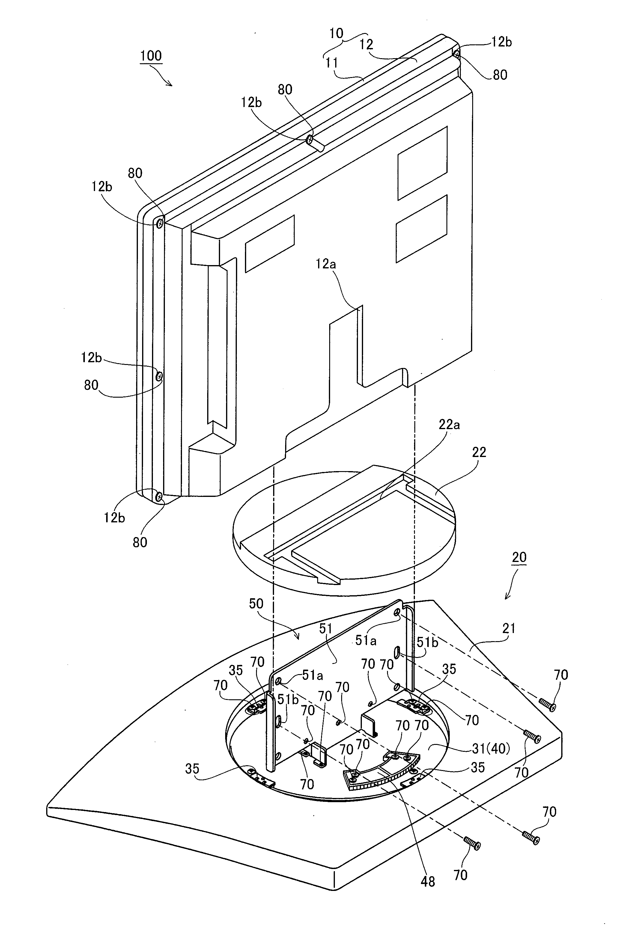
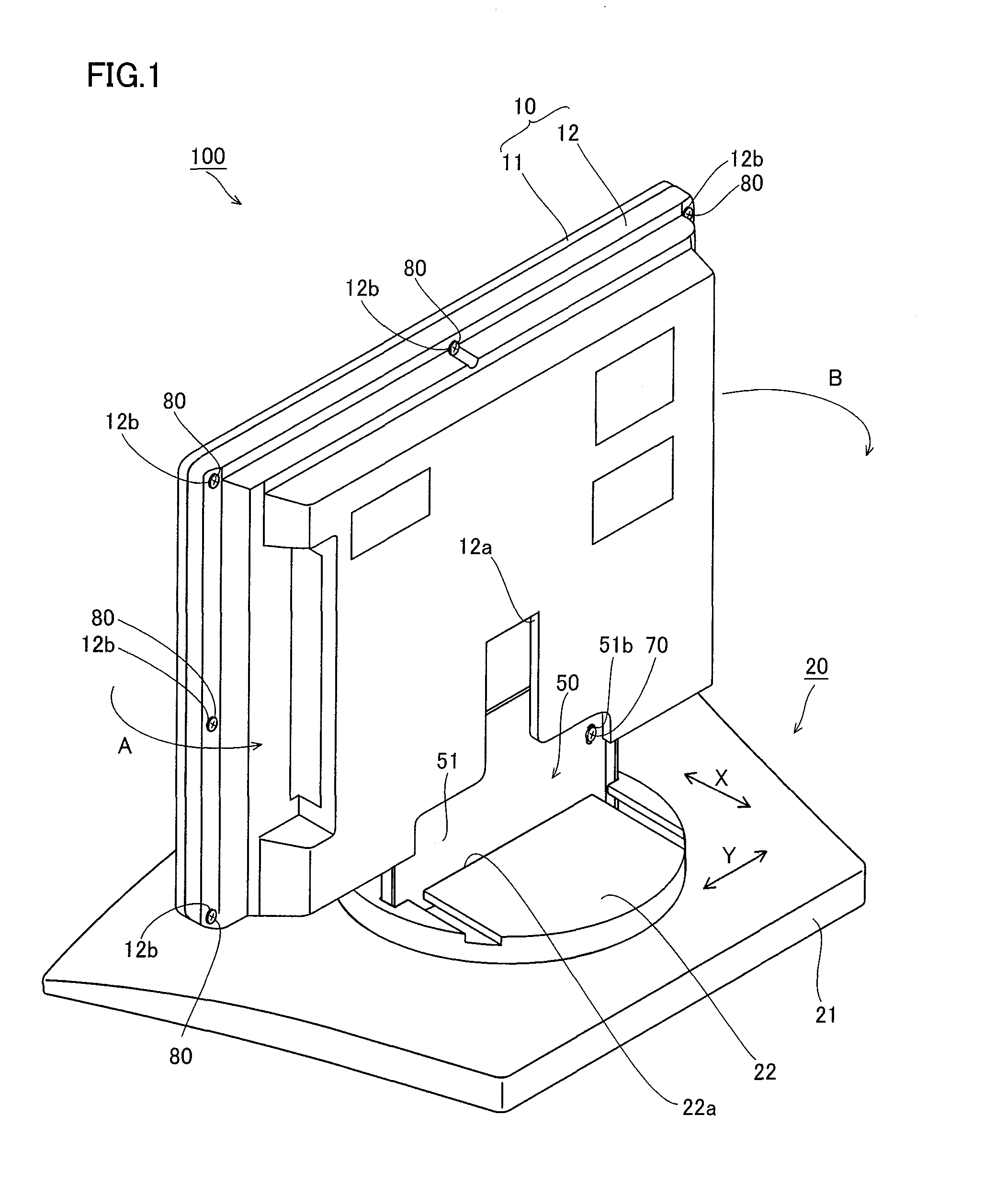
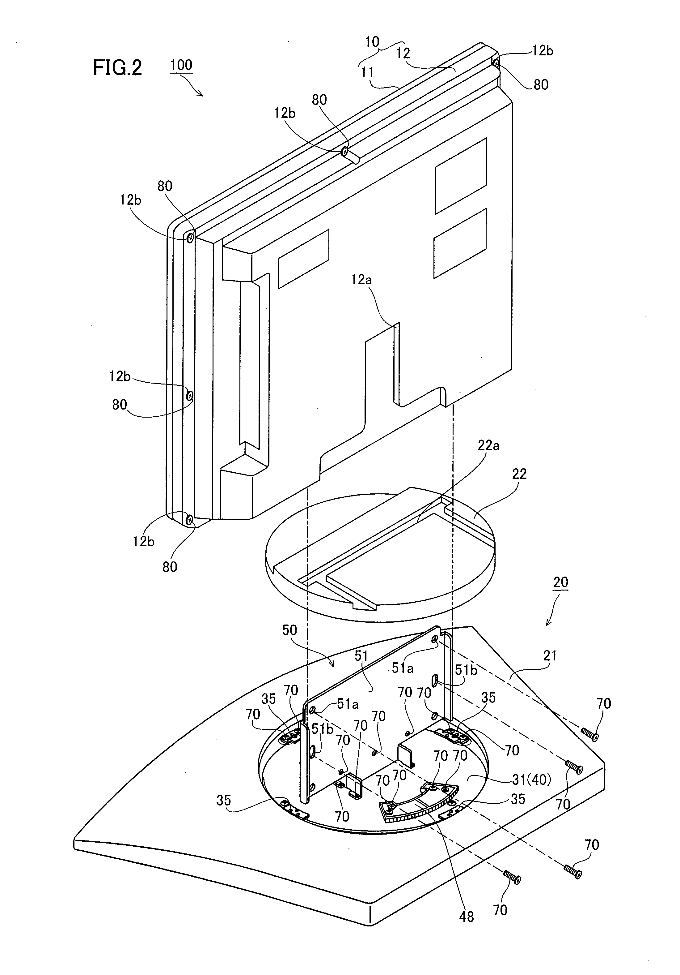
[0048]The structures of a display screen turning apparatus 20 according to an embodiment of the present invention and a liquid crystal television 100 provided with the display screen turning apparatus 20 are described with reference to FIGS. 1 to 12. This embodiment of the present invention is applied to the display screen turning apparatus 20 for the liquid crystal television 100 employed as an exemplary display. This liquid crystal television 100 comprises a display body 10 and the display screen turning apparatus 20 for turning the display body 10.

[0049]The display screen turning apparatus 20 according to the embodiment of the present invention is provided for turning the display body 10 in a direction A or B (by ±30° in the present invention). The display body 10 is an example of the “display screen” in the present invention. The display screen turning apparatus 20 is constituted of a tu...


PUM


Abstract

This display screen turning apparatus (base for a display screen) includes a platelike base member so formed as to receive the load of a display body applied to a display screen support mechanism on a partial region and to warp in a direction opposite to the direction of deflection resulting from the load of the display body with a prescribed amount of warpage when not receiving the load of the display body, and the prescribed amount of warpage is so set that the surface of the base member is substantially flattened when the base member receives the load of the display body applied to the display screen support mechanism.

Description

BACKGROUND OF THE INVENTION[0001]1. Field of the Invention[0002]The present invention relates to a base for a display screen, and more particularly, it relates to a base for a display screen comprising a platelike base member.[0003]2. Description of the Background Art[0004]A base for a display screen comprising a support member for supporting the display screen and a platelike base member is known in general. This base for a display screen is so formed that the platelike base member receives the load of the display screen applied to the support member on a partial region in the vicinity of the center thereof.[0005]Further, various structures of members receiving loads are proposed in general.[0006]For example, Japanese Patent Laying-Open No. 61-185946 (1986) discloses a structure of a metal mold formed by convexing die faces of a drag and a cope thereby flattening the die faces of the drag and the cope when pressing the drag against the cope.[0007]Japanese Patent Laying-Open No. 200...

Claims


Application Information

Patent Timeline
Patent Type & Authority Applications(United States)
IPC IPC(8): H04N5/64
CPCF16M11/00F16M11/08F16M2200/08F16M11/18F16M11/22F16M11/12
Inventor YOKOTA, KATSUYUKIHIBI, TOSHIHARU
Owner FUNAI ELECTRIC CO LTD
Why Eureka
Try Eureka