Bleed Structure For A Bleed Passage In A Gas Turbine Engine

a gas turbine engine and bleed structure technology, which is applied in the direction of combination engines, machines/engines, mechanical apparatus, etc., can solve the problems of negative effect on engine stability or efficiency

Active Publication Date: 2008-05-22
VOLVO AERO CORP
View PDF17 Cites 21 Cited by
  • Summary
  • Abstract
  • Description
  • Claims
  • Application Information

AI Technical Summary

Benefits of technology

[0008]It is desirable to achieve a bleed structure for a gas turbine engine, which creates conditions for an effective bleed while not negatively influencing the operation of the engine or at least keep the negative effects to a minimum. More specifically, it is desirable to improve the flow distribution in the bleed passage with no substantial negative effects on the gas flow in a gas duct from which the air is bled and / or in a gas duct into which the bled air is introduced.
[0010]Such an opening configuration at a bleed passage outlet creates conditions for a more favorable pressure distribution in a gas flow in the bleed passage. Likewise, such an opening configuration at a bleed passage inlet creates conditions for a more favorable pressure distribution in the bleed passage.
[0011]The opening configuration is especially advantageous in applications for bleed between a primary gas duct and a secondary gas duct where a pressure difference is small between a compressor portion and the secondary gas duct (fan duct) in order to secure bleed through-flow to a sufficient extent and in the intended direction. The opening configuration is further advantageous in applications where there is a limited space available for the bleed opening.
[0014]According to a further aspect of the invention, the other of the first and second wall portions is flush with the adjacent surfaces of the structure. This opening configuration at the outlet creates conditions for substantially not negatively effecting the passing gas flow in the gas duct into which the bleed air is introduced.
[0015]According to a further aspect of the invention, one of the first and second wall portions is lowered relative to the adjacent surfaces of the structure. This opening configuration at the inlet creates conditions for substantially not negatively effecting the passing gas flow in the gas duct from which the bleed air is extracted.

Problems solved by technology

There is a risk that the bleed air will negatively effect the stability or efficiency of the engine or cause vibration problems.
This increased pressure creates a non-uniform distribution of the bled gas flow, which leads to losses.

Method used


Image

  • Bleed Structure For A Bleed Passage In A Gas Turbine Engine
  • Bleed Structure For A Bleed Passage In A Gas Turbine Engine
  • Bleed Structure For A Bleed Passage In A Gas Turbine Engine

Examples


first embodiment

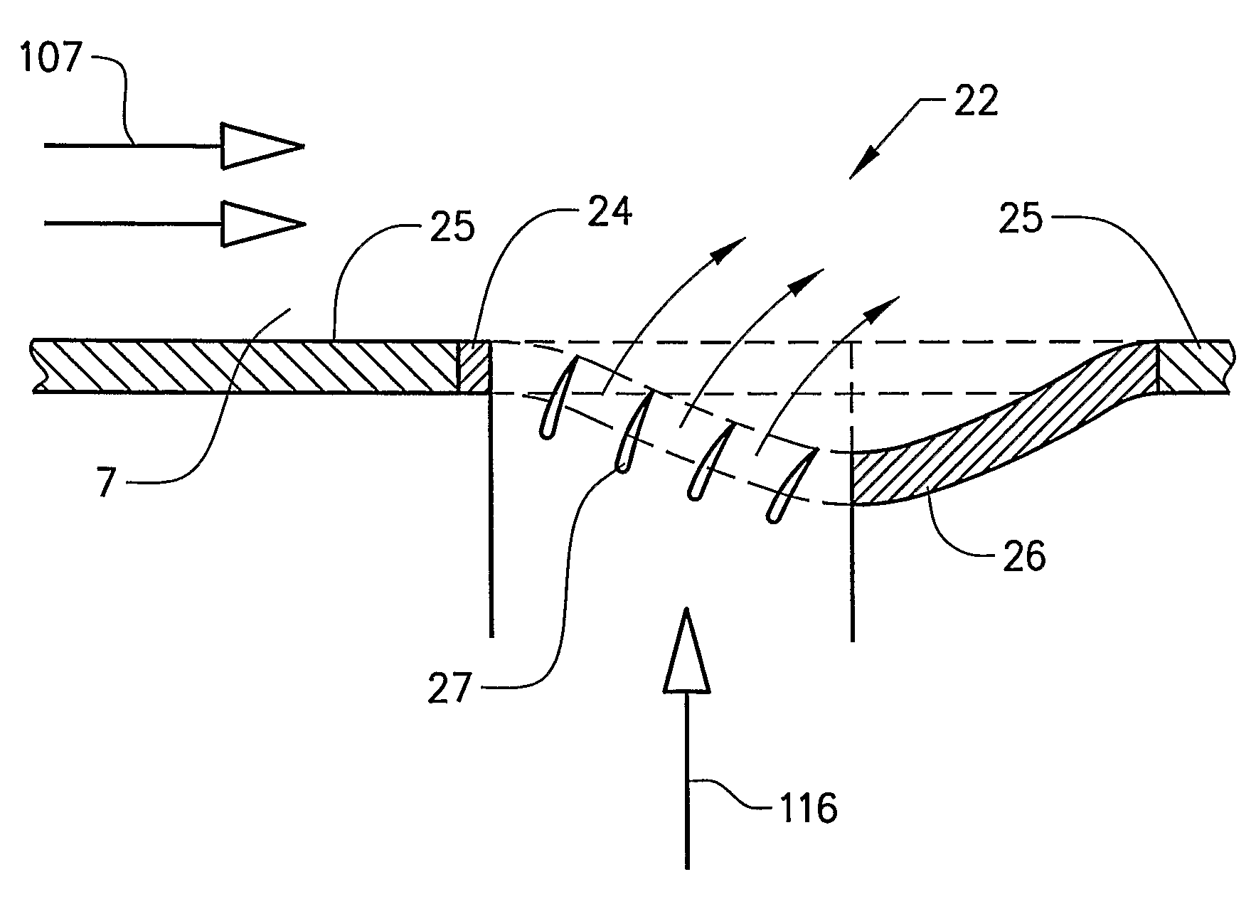
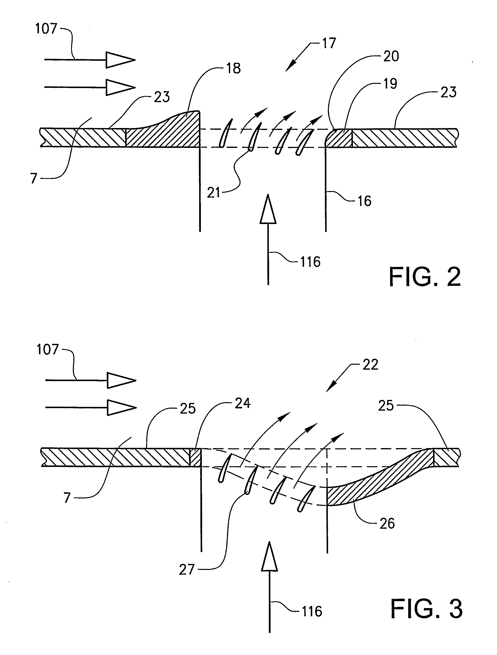
[0034]FIG. 2 shows a cut side view of a bleed structure 17 forming a bleed passage outlet to the secondary gas duct 7. The structure 17 comprises a first, upstream wall portion 18 forming a leading edge of the outlet. The structure 17 further comprises a second, downstream wall portion 19 forming a trailing edge of the outlet. The first and second wall portions 18, 19 end at different distances in the extension direction of the passage 16.

[0035]The wall 23 defining the gas duct 7 is substantially at the same level across the bleed opening (outlet). Thus, the wall 23 extends along a substantially straight line across the opening.

[0036]More specifically, the upstream wall portion 18 is raised relative to the adjacent surfaces of the structure and the gas duct wall 23. Further, the upstream wall portion 18 is raised relative to the downstream wall portion 19 so that a gas flow 107 in the duct 7 is directed somewhat radially away from the outlet and thereby creating a low pressure regio...

second embodiment

[0054]FIG. 12 illustrates a bleed passage inlet structure 40. The inlet bleed structure 40 is arranged in a wall 41 defining a gas duct 42 from which gas is extracted. The structure 40 comprises a first, upstream wall portion 43 and a second, downstream wall portion 44. The upstream wall portion 43 is substantially flush with the adjacent surfaces of the structure and the gas duct wall 34. Further, an end 45 of the upstream wall portion 43 facing the inlet is chamfered defining a flow path for the bleed gas from the gas duct 42 to a bleed passage 46. The upstream wall portion 43 is smoothed and aerodynamically rounded for reducing discontinuities in the gas duct flow. A plurality of airfoils 47 are arranged in parallel to each other in the inlet for guiding a bleed gas flow from the gas duct 42.

[0055]The downstream wall portion 44 is raised relative to the adjacent surfaces of the structure and the gas duct wall 41. Further, the downstream wall portion 44 is raised relative to the u...


PUM


Abstract

A bleed structure for a bleed passage in a gas turbine engine includes a first wall portion defining a first side of an opening for the passage, and a second wall portion defining a second side, opposite the first side of the opening. The first and second wall portions end at different positions in an extension direction of the opening.

Description

BACKGROUND AND SUMMARY[0001]The present application claims benefit of U.S. Provisional Application 60 / 593941, filed Feb. 25, 2005, and claims priority to International Application PCT / SE2005 / 000452, filed Mar. 24, 2005, both of which are incorporated by reference. The present invention relates to a bleed structure for a bleed passage in a gas turbine engine, the structure comprises a first wall portion defining a first side of an opening for the passage and a second wall portion defining a second side, opposite the first side of the opening. The bleed structure is intended to be arranged in the gas turbine engine so that the first wall portion is located upstream of the bleed passage opening and the second wall portion is located downstream of the opening.[0002]The bleed structure may be used in stationary gas turbine engines, but is especially advantageous for aircraft jet engines. Jet engine is meant to include various types of engines, which admit air at relatively low velocity, ...

Claims


Application Information

Patent Timeline
Patent Type & Authority Applications(United States)
IPC IPC(8): F02K3/02F02K3/075
CPCF02C3/13F02C6/08F02C9/18F05D2250/314F05D2250/52F05D2240/12F02K3/075
Inventor MARTENSSON, HANSNILSSON, MARTIN
Owner VOLVO AERO CORP
Why Eureka
Try Eureka