

Radial flow adsorber ‘U’ configuration
a technology of adsorption unit and radial flow, which is applied in the direction of separation process, dispersed particle separation, chemistry apparatus and processes, etc., can solve the problems of increasing the overall capital cost, increasing the overall pressure drop through the vessel, and non-uniform flow distribution, so as to reduce the capital and operating cost of the unit, and avoid the congestion of the head having the gas outlet
Active Publication Date: 2017-08-15
AIR PROD & CHEM INC
View PDF36 Cites 10 Cited by
- Summary
- Abstract
- Description
- Claims
- Application Information
AI Technical Summary
Benefits of technology
The U-flow configuration provides more uniform flow distribution and reduces congestion around gas inlets and outlets, making the unit easier to construct, maintain, and transport, while avoiding the need for post-weld heat treatment and minimizing the complexity of pipework layout.
Problems solved by technology
A feature of a typical Z-flow configuration in a radial flow adsorption unit is unequal pressure drop along the length of the adsorbent bed which leads to non-uniform flow distribution.
However, incorporating such internal components typically complicates the design of the unit, thereby increasing the overall capital costs, and increases the overall pressure drop through the vessel, thereby increasing the overall operating costs.
While the radial flow adsorption units disclosed in U.S. Pat. No. 5,814,129A represent an improvement over typical units configured for Z-flow because of the improved flow distribution through the adsorbent bed, the design of the unit is still more complicated than ideal and the presence of the cylindrical baffle increases overall pressure drop through the vessel.
However, the units are complicated mechanically which increases the capital cost.
Height is a particular issue for units configured for Z-flow since such units tend to have their inlets and outlets at opposite ends of the units.
However, the size of the pipework means that the head having the inlet and the outlet can be very congested which limits the options for the layout of the pipework.
The size of the units is such that the furnace often has to be built around the unit.
Since radial flow adsorption units are usually fabricated in a factory and then transported to site at least in part by road using a flatbed lorry, larger diameter units tend to be more difficult to transport, e.g. on narrow roads with low bridges.
Method used
View moreImage
Smart ImageViewing Examples

Examples
example
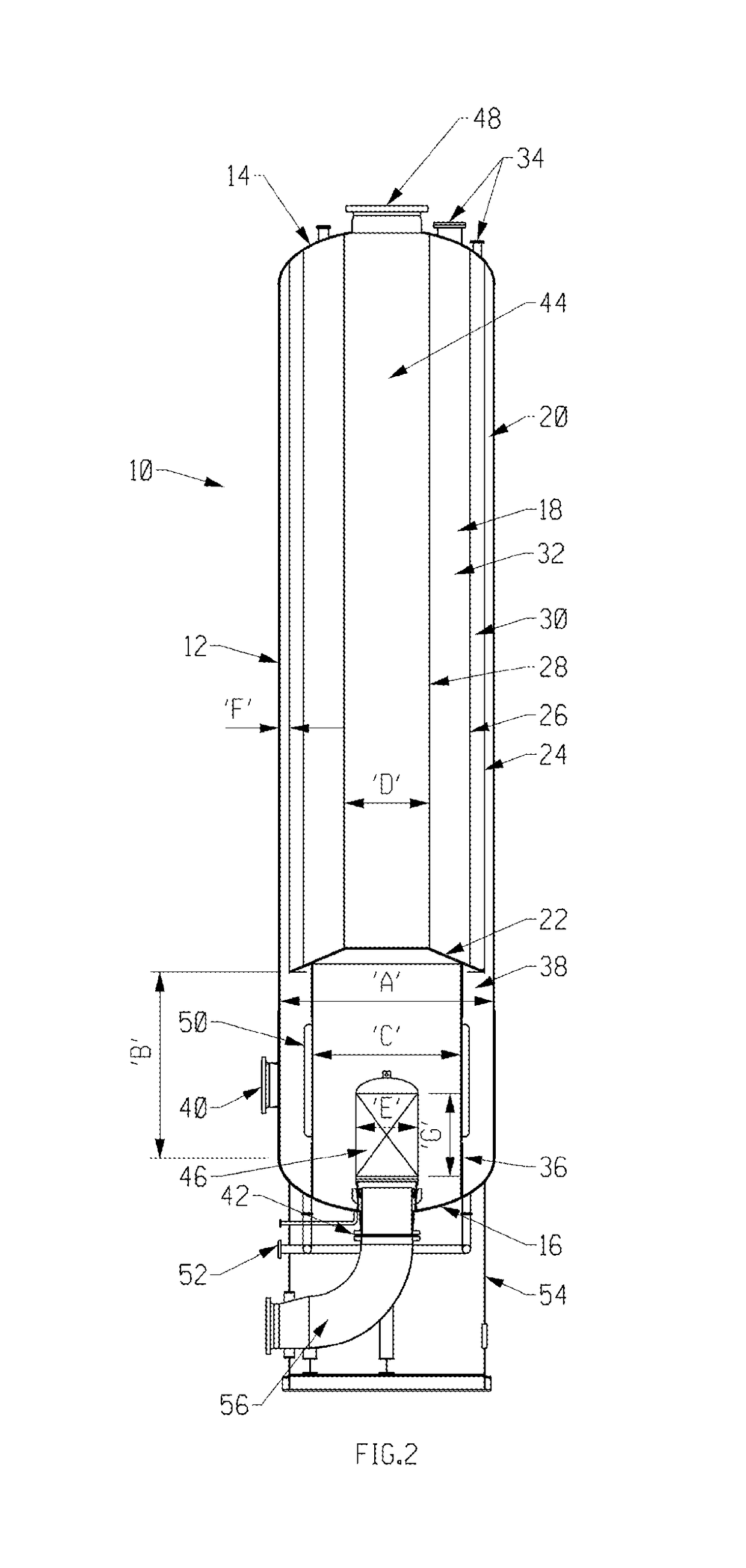
[0255]Computer simulations of the air purification process of U.S. Pat. No. 5,855,650A under the conditions identified in Table 1 of that reference have been carried out using proprietary software and data, and have identified the following preferred conditions of operation of the unit depicted in FIG. 2:
[0256]
Disclosed Apparatus and ProcessProcess conditionsUnitPreferredMost preferredOn-stream timemin100 to 250120 to 200Purge to air ratio—0.1 to 0.50.1 to 0.3Air FlowKg / s 50 to 300100 to 250Feed CO2 concentrationppm 100 to 2000300 to 600Feed temperatureC. 5 to 5010 to 30Feed pressurebar 1 to 404 to 7Hot regeneration temperatureC.100 to 300140 to 200Hot purge durationmin20 to 7025 to 50
Login to View More PUM
| Property | Measurement | Unit |
|---|---|---|
| pressure | aaaaa | aaaaa |
| pressure | aaaaa | aaaaa |
| thickness | aaaaa | aaaaa |
Abstract
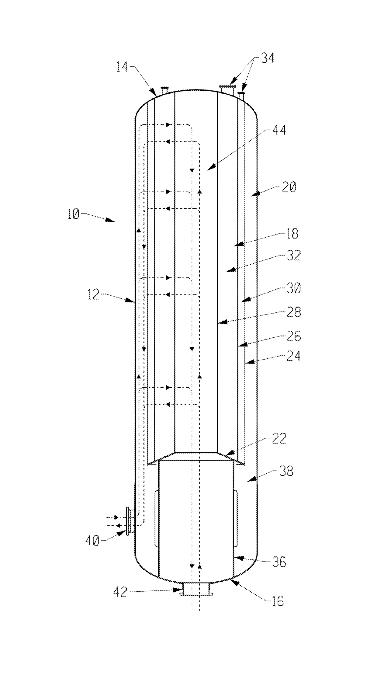
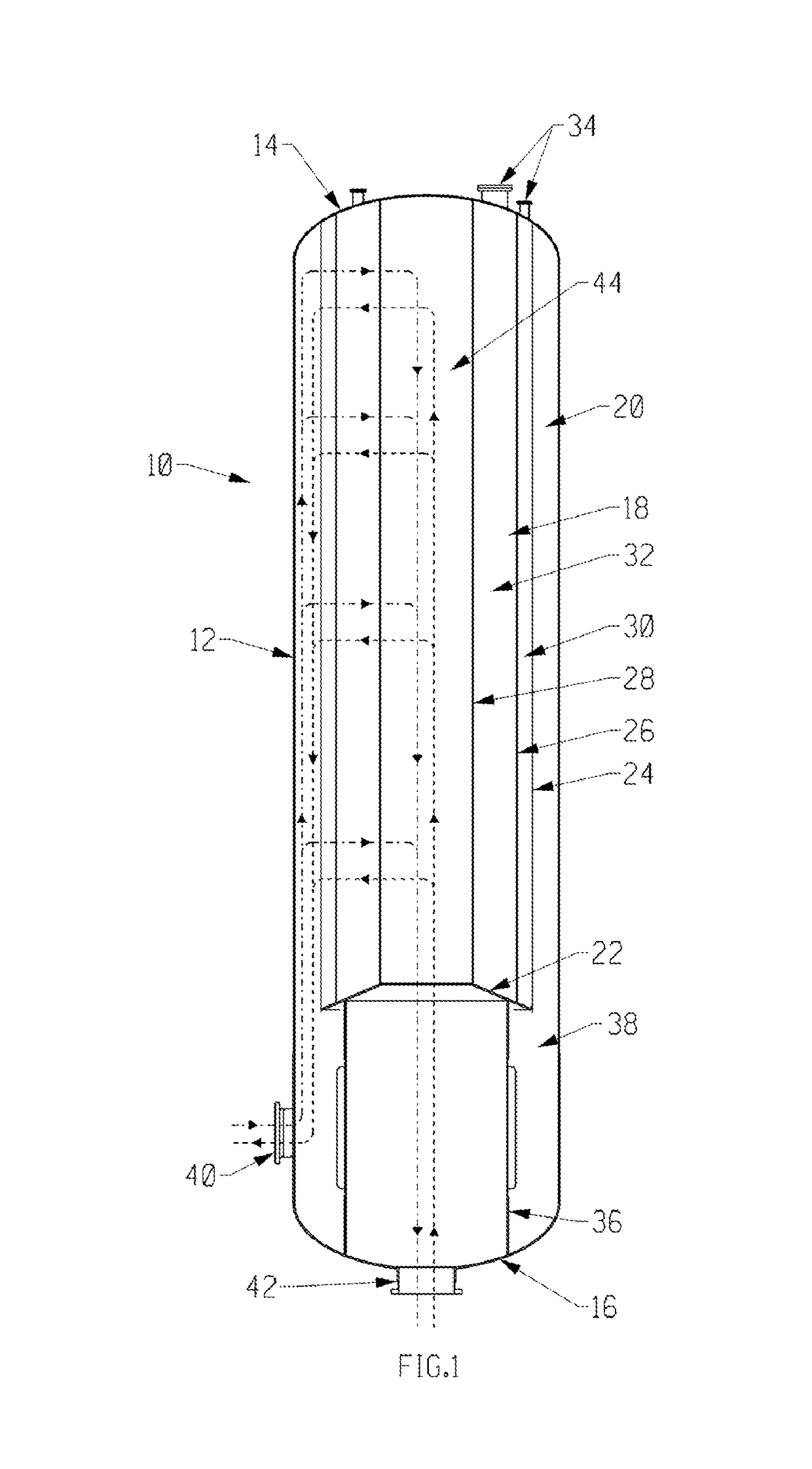
A radial U-flow adsorption unit for air purification in a TSA process, having a gas outlet at one end and at least one gas inlet at the side, preferably at the same end of the unit as the gas outlet. The simpler design of the unit facilitates manufacture, installation and transport, and reduces the capital and operating costs.
Description
BACKGROUND OF THE INVENTION[0001]The present invention relates to radial flow adsorption units for separating a gaseous component from a gas mixture, and particularly for purifying air prior to cryogenic distillation. The invention is primarily concerned with units configured for U-flow operation.[0002]It is standard practice in the cryogenic air separation industry to use radial flow adsorption units for removing contaminants such as water, carbon dioxide, trace hydrocarbons and NOx from the air feed to the cryogenic air separation plant to avoid issues with plant operation and safety.[0003]A radial flow adsorption unit for air purification is typically a vessel having an outer tubular side wall that is closed at each end with a respective end wall, containing an elongated annular bed of at least one adsorbent material located co-axially within the interior of vessel. There is usually an annular space defined by the inside surface of the outer wall and the outside surface of the an...
Claims
Login to View More Application Information
Patent Timeline
 Patent Type & AuthorityPatents(United States)
IPC IPC(8): B01D53/02B01D53/04B01D53/86
CPCB01D53/0431B01D2259/40081Y02C10/08Y02C20/10B01D53/0446B01D53/864B01D2253/108B01D2253/34B01D2256/12B01D2257/402B01D2257/404B01D2257/504B01D2257/702B01D2257/80Y02C20/40B01D53/04B01J8/02
InventorKALBASSI, MOHAMMAD ALIGIBBON, STEPHEN JOHNMALIK, NASIM UL HASSANTENTARELLI, STEPHEN CLYDE
OwnerAIR PROD & CHEM INC