
Method for automatic shimming for nuclear magnetic resonance spectroscopy

a nuclear magnetic resonance spectroscopy and automatic shimming technology, applied in the direction of reradiation, amplifiers, transmission, etc., can solve the problems of difficult automatic analysis of the spectrum obtained from any but a very simple sample, and the process is far too time-consuming

Inactive Publication Date: 2008-05-22
BRUKER SWITZERLAND AG
View PDF3 Cites 36 Cited by
  • Summary
  • Abstract
  • Description
  • Claims
  • Application Information

AI Technical Summary

Benefits of technology

The technical effect of this patent is to provide a way to connect better the impact of certain functions used during magnetic resonance imaging (MRI) with the resulting quality of the MRI image.

Problems solved by technology

The technical problem addressed in this patent text is to improve the homogeneity of the magnetic field in a magnetic resonance apparatus for NMR spectroscopy. The conventional methods of shimming (adjusting the magnetic field to compensate for inhomogeneity) involve multiple iterations and are time-consuming. The proposed method aims to create an optimal solution for the residual field distribution to minimize the inhomogeneity of the magnetic field. However, the residual field cannot be perfectly eliminated, leading to different solutions for the same criterion. The method uses a projection approach to describe the effect of the shim coils on the magnetic field distribution, but the fit procedure is not unambiguous. Gradient shimming is also used, but the algorithm used for optimizing the shim currents is not straightforward. The main disadvantage of the described method is the limited convergence of the iterative shimming procedure due to the residual field distribution.

Method used


Image

  • Method for automatic shimming for nuclear magnetic resonance spectroscopy
  • Method for automatic shimming for nuclear magnetic resonance spectroscopy
  • Method for automatic shimming for nuclear magnetic resonance spectroscopy

Examples


Embodiment Construction

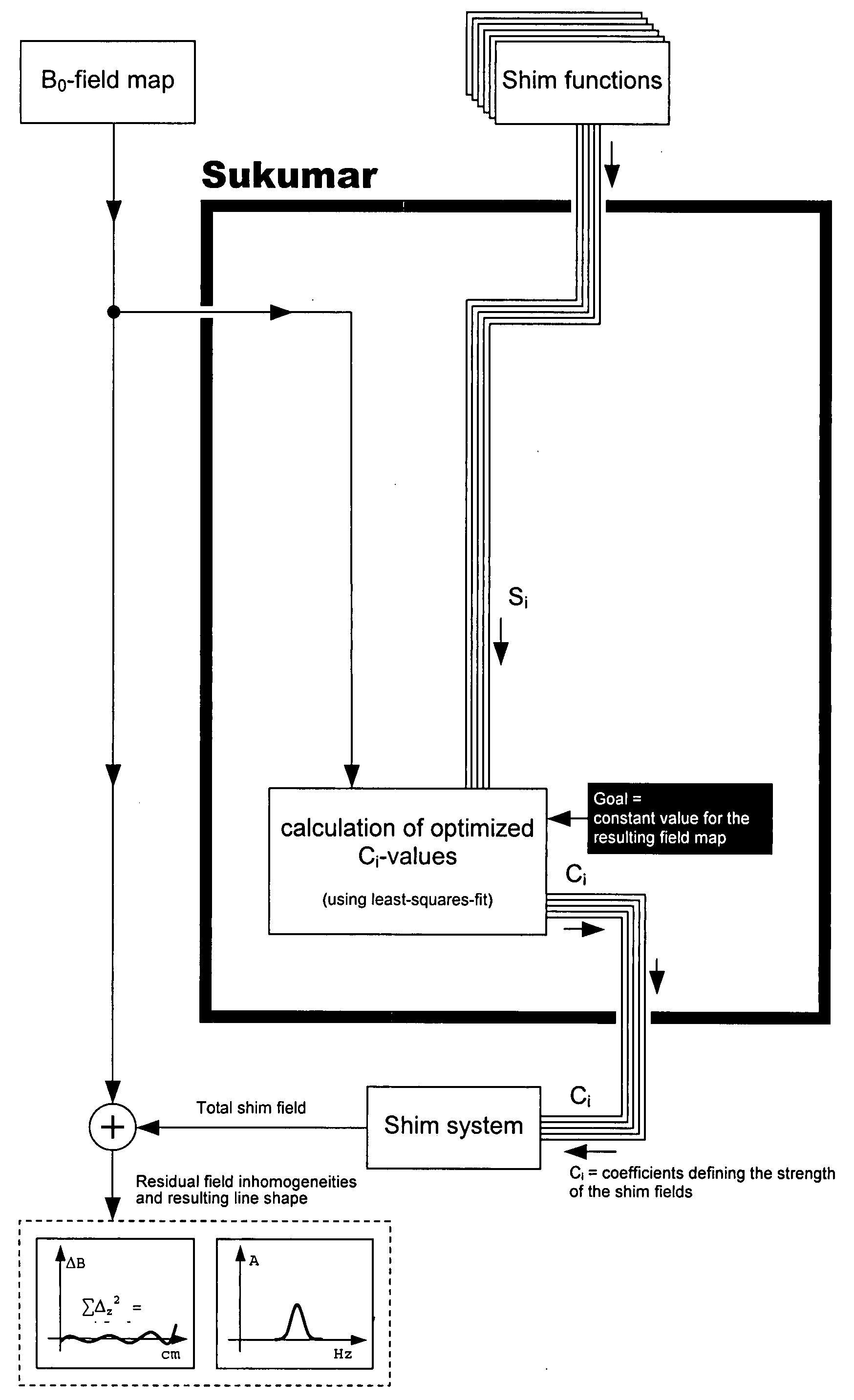
[0068]FIG. 1 shows the main building blocks of the NMR Spectrometer. The NMR Spectrometer comprises an experimental magnet area 1, a spectrometer area 2 with electronic components, and a computer 3 for controlling and evaluating the experiment. The experimental parameters such as gradient pulses and RF pulses and shim values as requested by the computer 3 are realised by gradient coils 4, RF coils 5 and shim coils 6 respectively within the magnet area 1 via the spectrometer area 2. The NMR signal received from a sample 7 is transferred to the computer 3, usually in a digitised form. In most cases, RF coils 5 and gradient coils 4 are part of a probe head, whereas the shim coils 6 are mounted in the magnet bore.

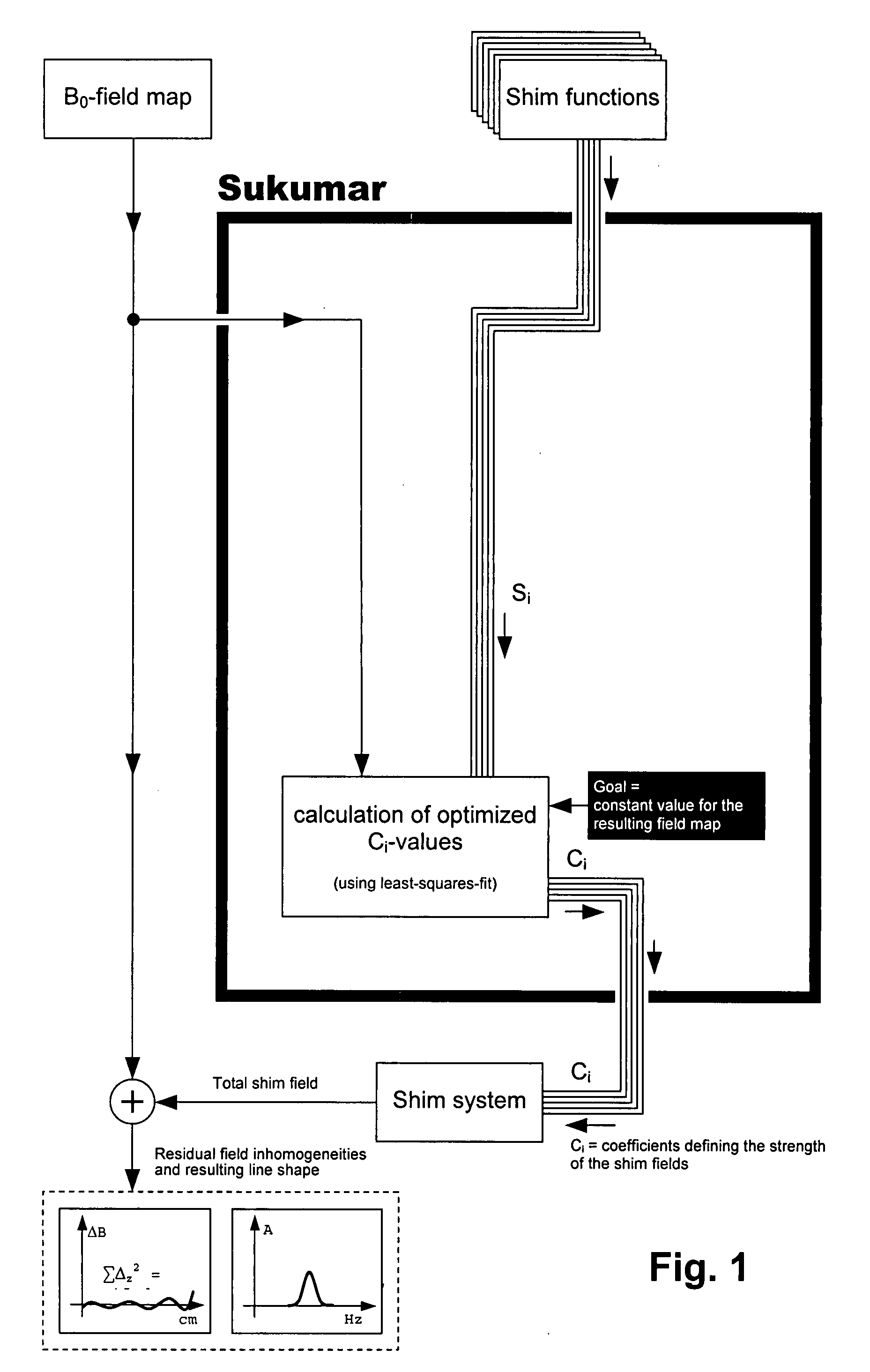
[0069]FIG. 2 shows a flow chart of the iterative approach used with conventional search and gradient shimming methods. From the data obtained in an NMR measurement a criterion is calculated. If the result fulfils the requirements the procedure is stopped, otherwise new shim cur...


PUM


Abstract

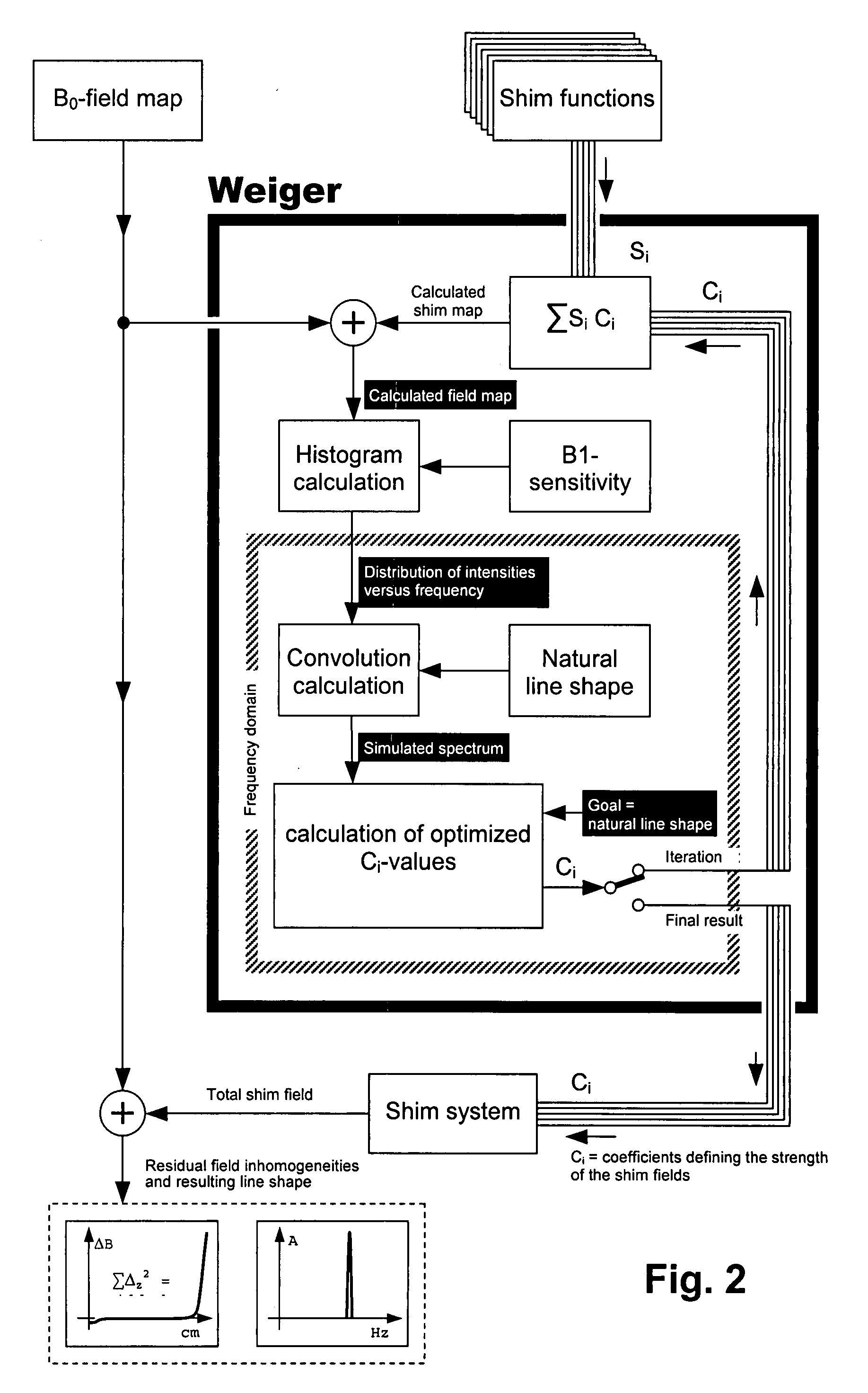
A method for homogenizing a static magnetic field with a magnetic field distribution B0(r) for nuclear magnetic resonance spectroscopy by adjusting the currents Ci through the shim coils, thus creating spatial field distributions Ci·Si(r), where r stands for one, two, or three of the spatial dimensions x, y, and z, and said magnetic field distribution B0(r) has only a field component along z, in a working volume of a magnetic resonance apparatus with one or more radio frequency (=RF) coils (5) for inducing RF pulses and receiving RF signals within a working volume, said RF coils having a spatial sensitivity distribution of magnitudes B1k(r), and with shim coils (6) for homogenizing the magnetic field within the working volume, said shim coils (6) being characterized by their magnetic field distributions per unit current Si(r) and having components only along z, includes the following steps:
    • (a) Mapping the magnetic field distribution B0(r) of the main magnetic field,
    • (b) calculating a simulated spectrum IS(f) based on the sum of the magnetic field distribution B0(r) and the additional field distributions Ci·Si(r) generated by the shim coils (6), and on the sensitivity distributions B1k(r) of the RF coils(5),
    • (c) optimising a quality criterion derived from the simulated spectrum IS(f) by using an optimisation procedure within a search range with the shim currents Ci as a set of parameters, whereby for each new set of parameter values step (b) has to be repeated,
    • (d) realising the found optimum of the quality criterion of step (c) by generating the associated target field distribution B0T(r).
In this way a direct one-to-one link is obtained between a set of shim currents and the associated NMR spectrum The quality of the desired NMR spectra can be improved with this method.

Description


Claims


Application Information

Patent Timeline
Owner BRUKER SWITZERLAND AG
Learn More