
Method For Detecting Target Sound, Method For Detecting Delay Time In Signal Input, And Sound Signal Processor

a delay time and target sound technology, applied in the field of target sound detection, can solve the problems of affecting the practical application of voice recognition systems, affecting the recognition rate, and users suffering great burden and discomfort from close-talking microphone headsets, so as to achieve high resistance to environmental fluctuations

Inactive Publication Date: 2008-05-22
YAMAHA MOTOR CO LTD +1
View PDF8 Cites 18 Cited by
  • Summary
  • Abstract
  • Description
  • Claims
  • Application Information

AI Technical Summary

Benefits of technology

[0011]To overcome the problems described above, preferred embodiments of the present invention provide a method for detecting a target sound, a method for detecting a delay time in signal input, a sound signal proc

Problems solved by technology

However, when it comes to voice recognition in actual environments, the recognition rate is inferior because of the mismatch between learning data and observed data in their environments, contents of speech, and other factors.
In addition, users suffer great burden and discomfort from a close-talking microphone headset as a sound reception system worn by the user.
This significantly hinders the practical application of voice recognition systems.
However, such studies have shown that it is difficult to recognize the remote voices because of their lower S / N ratio, influences of background noise and room reverberation, and other factors.
However, this method requires plural microphones to be fixed at regular intervals for accurate identification processing of the direction of the speaker, and thus, downsizing and mobilization of such a method is difficult.
Therefore, there is a problem that this method is difficult to apply to voice input in various environments and under various circumstances and thus has limited uses.

Method used


Image

  • Method For Detecting Target Sound, Method For Detecting Delay Time In Signal Input, And Sound Signal Processor
  • Method For Detecting Target Sound, Method For Detecting Delay Time In Signal Input, And Sound Signal Processor
  • Method For Detecting Target Sound, Method For Detecting Delay Time In Signal Input, And Sound Signal Processor

Examples


Embodiment Construction

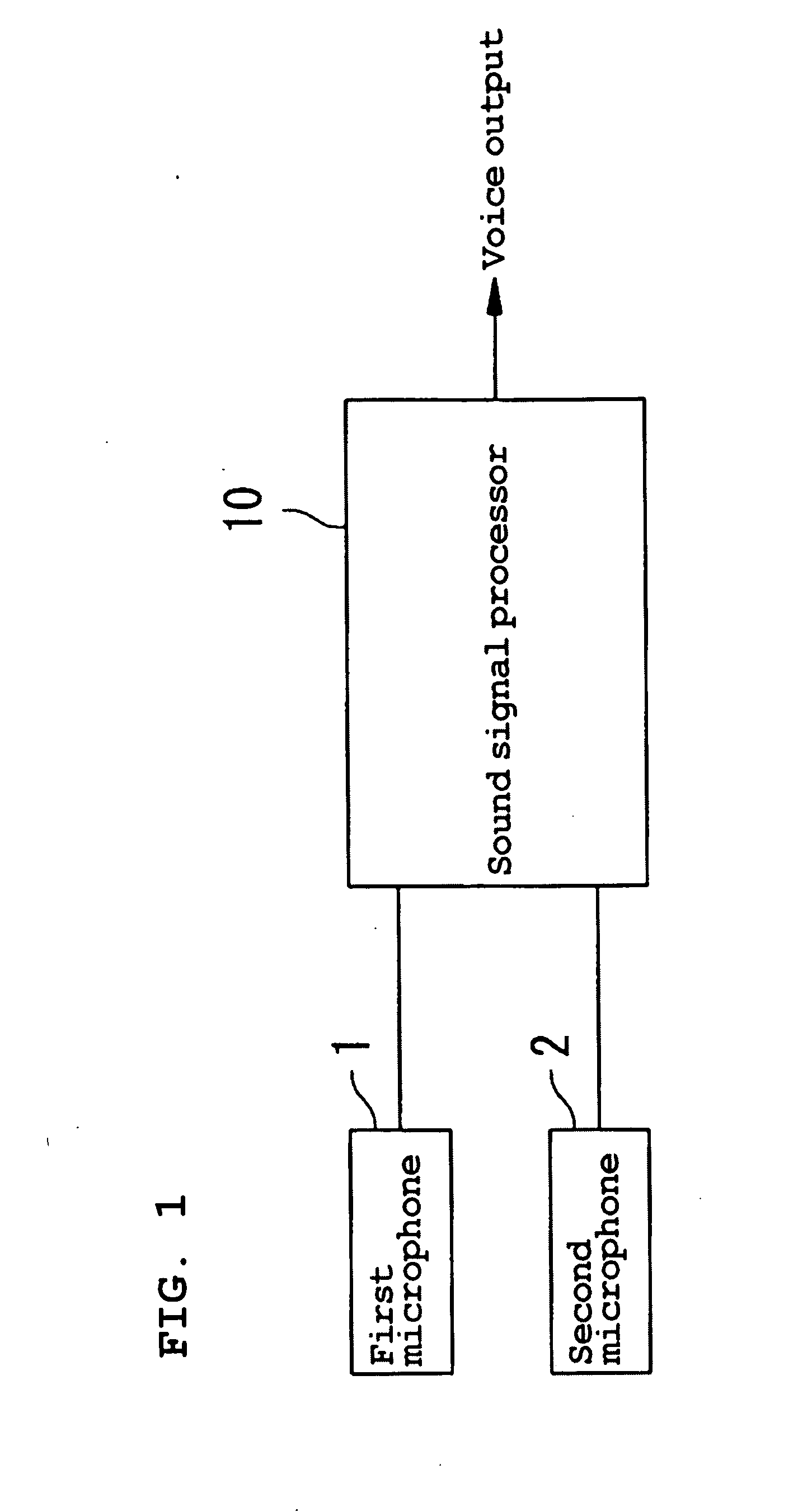
[0052]A preferred embodiment of the present invention is described below with reference to the drawings. As shown in FIG. 1, this preferred embodiment is a sound signal processor 10 for processing sound signals picked up by two microphones 1 and 2. The first and second microphones 1 and 2 are preferably of a mountable type that can be mounted to a sound source (user) with a comparatively high degree of freedom in mounting locations.

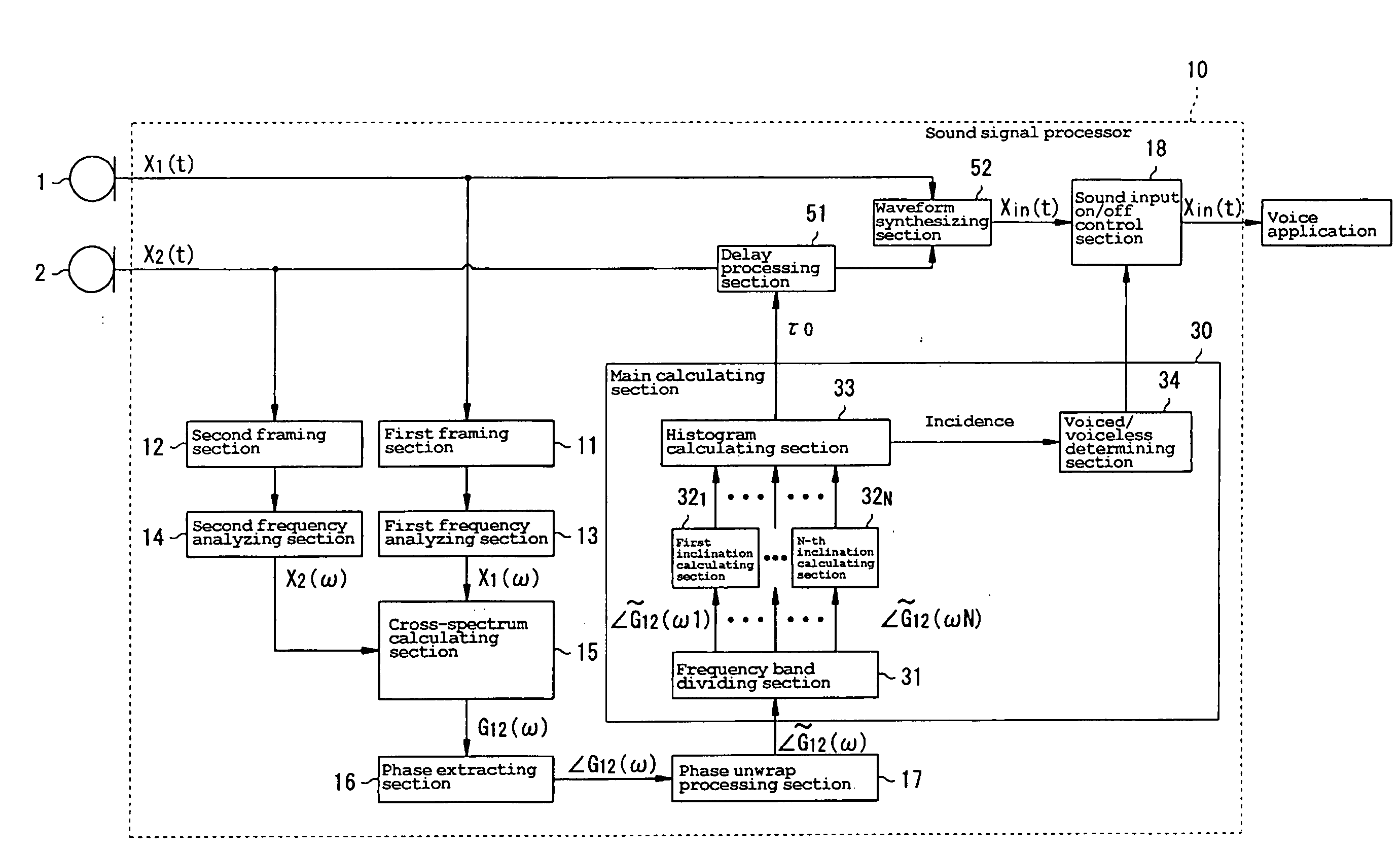
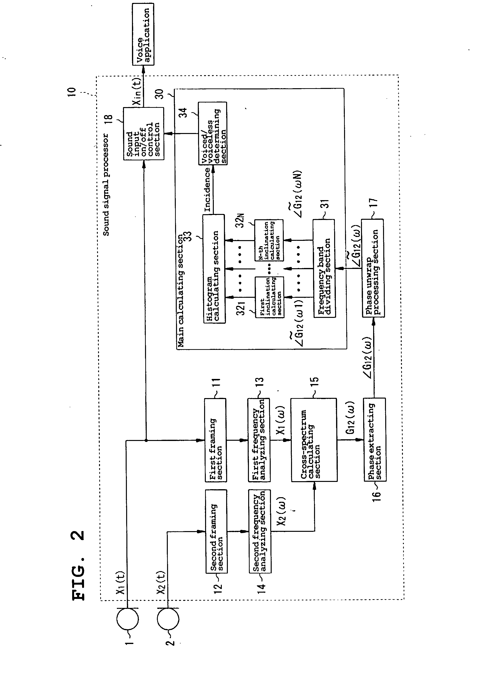
[0053]FIG. 2 shows the construction of the sound signal processor 10 of a first preferred embodiment. As shown in FIG. 2, the sound signal processor 10 includes first and second framing sections 11 and 12, first and second frequency analyzing sections 13 and 14, a cross-spectrum calculating section 15, a phase extraction processing section 16, a phase unwrap processing section 17, a main calculating section 30, and a sound input on / off control section 18. The main calculating section 30 includes a frequency band dividing section 31, first through N-th inc...


PUM


Abstract

A sound signal processor includes first and second framing sections, first and second frequency analyzing sections, and a cross-spectrum calculating sections, for detecting the phase of a cross-spectrum between the sound signals input to first and second microphones, a phase extracting sections, a phase unwrap processing sections, a frequency band dividing section, and first through N-th inclination calculating sections, for detecting the inclinations of the phase of the cross-spectrum detected by the cross-spectrum calculating section with respect to the frequency, and a histogram calculating section and a voiced / voiceless determining section, for detecting a speech section in the sound received by the first and second microphones based on the inclination with respect to the frequency detected by the first through N-th inclination calculating sections.

Description

BACKGROUND OF THE INVENTION[0001]1. Field of the Invention[0002]The present invention relates to a method for detecting a target sound and a program therefor, a method for detecting a delay time in signal input between sound signals input into plural microphones and a program therefor, a sound signal processor for processing input sound signals, and a voice recognition device for detecting a speech sound and processing voice recognition of the speech sound.[0003]2. Description of the Related Art[0004]In various forms of communication used by humans, voice is the most basic and preferred form of communication, with its information transmission speed higher than any other information transmission method. Thus, until recently, the voice has served as the basis of human communication since ancient times.[0005]There are proposed voice recognition techniques for recognizing the voice. Voice recognition includes extracting the most basic information on the semantic contents, or phonologica...

Claims


Application Information

Patent Timeline
IPC IPC(8): G10L21/02G10L25/03G10L15/04G10L15/28G10L21/0232G10L21/0264G10L25/78G10L25/84
CPCG10L15/20G10L2021/02166G10L21/0272
Inventor TAKEDA, KAZUYATATARA, KIYOSHIITAKURA, FUMITADA
Owner YAMAHA MOTOR CO LTD
Learn More