Telescopic table support

a technology for telescopic tables and supports, applied in the direction of variable height tables, rod connections, domestic objects, etc., can solve the problems of unintentional lowering affecting the stability of the table top, and the need for relatively high precision in the manufacture of components, etc., to achieve smooth raising and lowering, and the effect of low cos

a technology for telescopic tables and supports, applied in the direction of variable height tables, rod connections, domestic objects, etc., can solve the problems of unintentional lowering affecting the stability of the table top, and the need for relatively high precision in the manufacture of components, etc., to achieve smooth raising and lowering, and the effect of low cos

US20080121150A1Active Publication Date: 2008-05-29UNIFOR SPA

Image

  • Telescopic table support
  • Telescopic table support
  • Telescopic table support

Examples


Embodiment Construction

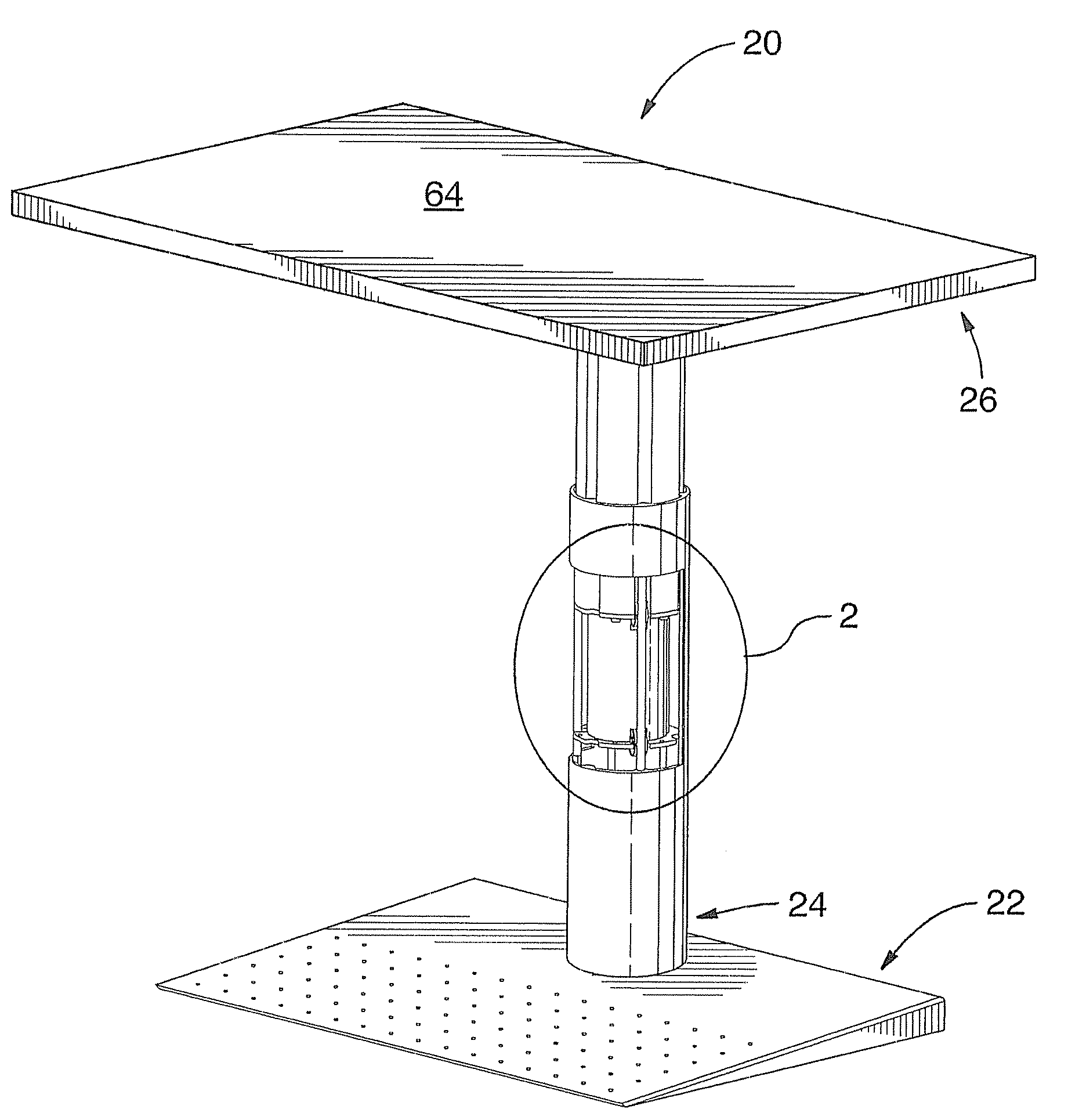
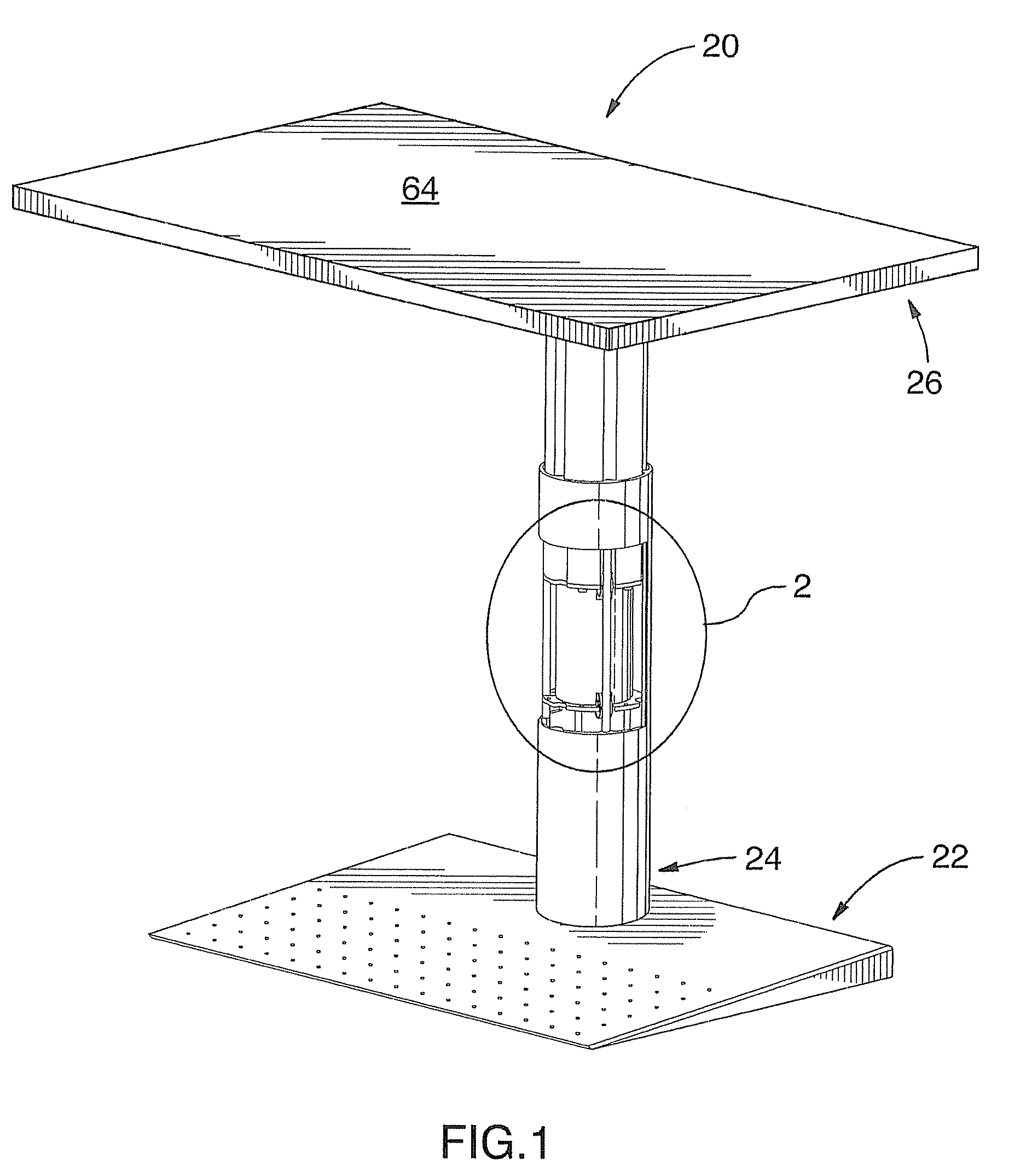
[0016]A height-adjustable pedestal-style table or desk constructed according to a preferred embodiment of the invention and designated with general reference numeral 20 is illustrated in partially-cut away perspective view in FIG. 1 and will be seen to comprise, generally, a foot 22, a telescopic support 24 and a desk or table top member 26.

[0017]The telescopic support 24, which will be described initially, is shown in exploded view in FIG. 3 and will be seen to comprise an outer leg part 28 and an inner leg part 30.

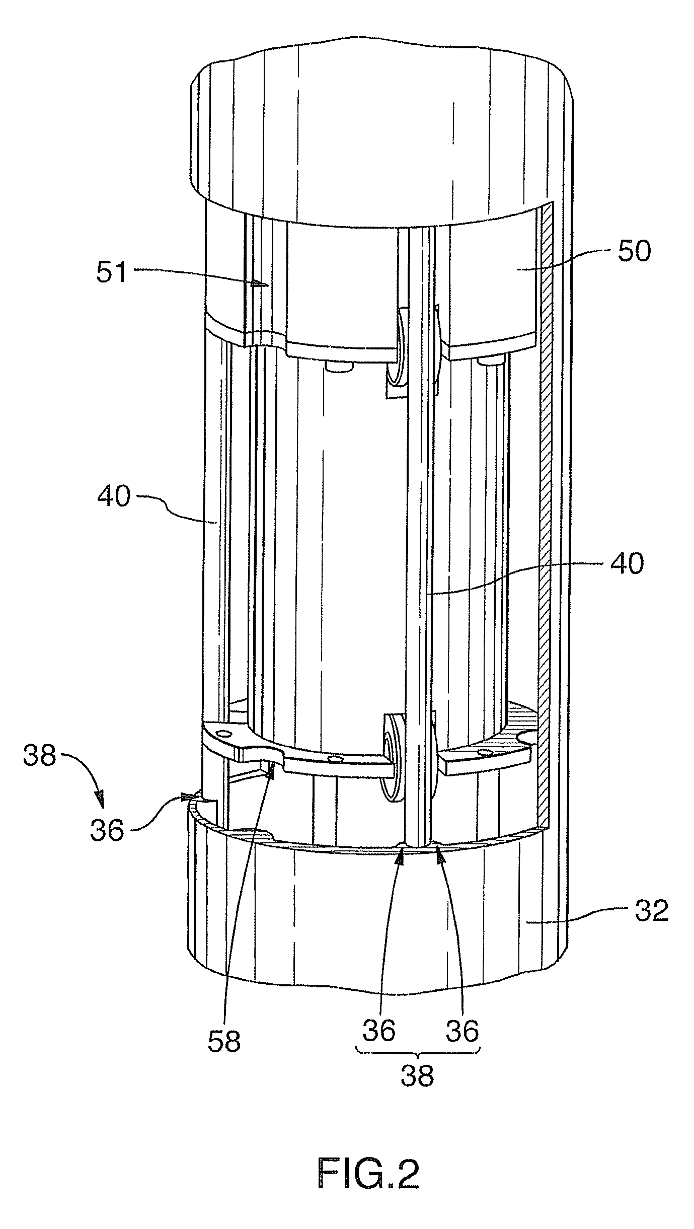
[0018]The outer leg part 28 has an extruded aluminum tubular body 32 which defines a longitudinal axis X-X and has an interior passage 34 through which the longitudinal axis X-X extends centrally. The body 32 is generally thin-shelled, but includes a plurality of longitudinally-extending stiffening ribs 36,36′, best seen in FIG. 8.

[0019]Six of these ribs 36 are disposed in three pairs 38, wherein the paired ribs 36 are closely-spaced to one another, the three pairs 38 be...


PUM


Abstract

A telescopic support is disclosed and has outer and inner leg parts. The outer leg part has: a tubular body defining a longitudinal axis and having an interior passage through which the axis extends centrally. The inner leg part has: a shuttle body part disposed at least partially in the tubular body; and rollers rotably mounted to the shuttle body to support the inner leg part for longitudinal reciprocating movement in the tubular body. The support can be secured to a base and topped with a work-surface defining member to form a height-adjustable table, as also disclosed.

Description

BACKGROUND OF THE INVENTION[0001]Table or desk tops are often supported by one or more telescopic supports, such that the table or desk top can be raised or lowered to meet the needs of users. A common application is an overbed table with vertical adjustability, as found in hospitals and the like.[0002]Typically, this functionality is met by providing inner and outer tubes separated by, preferably, a self-lubricating bearing material such as polytetrafluorethylene. While this arrangement provides adequate utility, in order to provide a telescopic support which extends and retracts smoothly, the components need to be manufactured with relatively high precision, which entails substantial costs.[0003]U.S. Pat. No. 4,381,095 (Kritske), issued Apr. 26, 1983, employs an alternate structure having four pairs of rollers spring-mounted to the inner tube and adapted to engage the inner surface of the outer tube. The resistance of the rollers to rolling movement is such that a table surface at...

Claims


Application Information

Patent Timeline
29 May 2008
Publication
US20080121150A1
IPC
F16M11/28; F16M11/00; A47B9/20; A47B27/14; F16B7/10
CPC
A47B9/04; A47B2220/0025; A47B13/023; A47B9/20
Inventors
PICCHIO, CESARE