Camera system for large vehicles

a camera system and vehicle technology, applied in the field of large vehicle cameras, can solve the problems of school buses, particular challenges, and risks to the safety of the vehicle and passengers boarding and disembarking from the vehicle, and achieve the effects of reducing the risk of accidents

Active Publication Date: 2008-05-29
ROSCO
View PDF23 Cites 127 Cited by
  • Summary
  • Abstract
  • Description
  • Claims
  • Application Information

AI Technical Summary

Benefits of technology

[0013]As shown for example in FIG. 1, the right rear view camera may be positioned at the right side of the vehicle anterior to the driver's area, the left rear view camera may be positioned at the left side of the vehicle anterior to the driver's area, the right side camera may be positioned at the right side of the vehicle posterior to the driver's area, and the left side camera may be positioned at the left side of the vehicle posterior to the driver's area. Each camera may be fixedly attached with respect to the vehicle in a stationary position and provides an unadjustable field of vision.

Problems solved by technology

Operating a vehicle, such as a larger passenger vehicle, entails particular difficulties and risks to the safety of the vehicle and the passengers boarding and disembarking from the vehicle.
Schoolbuses pose particular challenges because society has set high standards for protecting children.
Mirrors, however, present their own challenges.
Also, the mirrors and the assemblies on which they are mounted may introduce drag and may thus decrease fuel economy.
Also, mirrors do not provide a unified view inside the cabin for the driver.
Also, the driver must look outside of the cabin to view the mirrors positioned on the exterior of the vehicle, which necessitates looking through the side windows or a windshield, which may be dirty or wet or covered with snow or the like.
In addition, the mirrors will be typically quite dark in the early morning hours or in the evening hours.
Further, the driver may have to contend simultaneously with different lighting conditions, since the field of view of one of the external mirrors may be well lit at any particular time while the field of view of another mirror may be poorly lit or not lit at all.

Method used


Image

  • Camera system for large vehicles
  • Camera system for large vehicles
  • Camera system for large vehicles

Examples


Embodiment Construction

[0027]With reference to the above-described Drawings, various embodiments of the invention are described below.

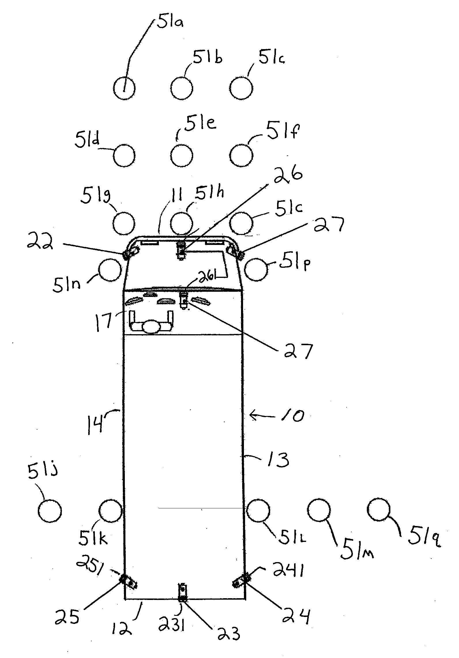
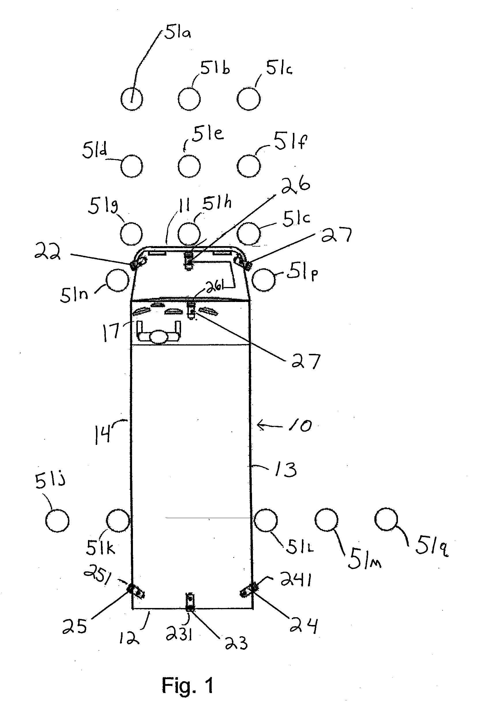
[0028]FIG. 1 shows a vehicle 10 in relation to cylindrical drums 51a-n and 51p-51q which Federal regulations require to be visible by the driver from the driver's cabin 17. The first nine cylindrical drums 51a-51i are positioned in three rows and three columns immediately in front of the vehicle. Accordingly, cylindrical drum 51h is positioned immediately in front of the vehicle and will typically be in the driver's blind spot in front of the hood. Conventionally, a cross-view mirror (not shown) would be positioned on the right side of the vehicle protruding away from a wall of the vehicle near the front, and would provide the driver with a view of cylindrical drum 51h. Drums 51n and 51p are positioned adjacent the left and right side, respectively, of the front of the vehicle, anterior to the driver's cabin 17. Drums 51j and 51k are positioned to the left of the vehicle mo...


PUM


Abstract

A vehicle-borne camera-based observation system for monitoring areas adjacent a vehicle or passenger vehicle, such as a bus or schoolbus, is disclosed, to provide safer operation for passersby, including for children, and driver convenience. The system includes several cameras, and several monitors in a driver's area displaying all of the fields of view from the cameras, such that each monitor may be controllable to show either the field of view of a first camera or a the field of view of a second camera, according to a driver selection or according to an automatic selection. Night vision, automatic tracking, and illumination systems are also provided.

Description

CROSS REFERENCE TO RELATED APPLICATIONS[0001]The present application claims benefit of and priority from U.S. Provisional Application Ser. No. 60 / 913,580 filed Apr. 24, 2007 entitled EXTERNAL SAFETY ILLUMINATION FOR A BUS, which is a continuation-in-part of U.S. Provisional Patent Application Ser. No. 60 / 857,250 filed Nov. 7, 2006 entitled MULTIPLE CAMERA SYSTEM FOR PROVIDING 360 DEGREE COVERAGE FOR SCHOOL BUSES, the entire contents of which applications are hereby incorporated by reference herein.FIELD OF THE INVENTION[0002]The present application generally relates to systems for enhancing a vehicle driver's view and systems for vehicle safety, including schoolbus safety.BACKGROUND OF THE INVENTION[0003]Operating a vehicle, such as a larger passenger vehicle, entails particular difficulties and risks to the safety of the vehicle and the passengers boarding and disembarking from the vehicle. Schoolbuses pose particular challenges because society has set high standards for protecting...

Claims


Application Information

Patent Timeline
Patent Type & Authority Applications(United States)
IPC IPC(8): B60Q9/00H04N7/18B60Q1/00
CPCB60Q1/24B60Q1/525B60Q5/006B60R1/00B60R2300/102G06K9/00791B60R2300/105B60R2300/406B60R2300/70B60R2300/8026H04N7/181B60R2300/103B60Q1/247B60Q1/249B60Q2800/30G06V20/56
Inventor ENGLANDER, BENJAMIN
Owner ROSCO
Why Eureka
Try Eureka