Dynamic rod

a rod and dynamic technology, applied in the field of cervical spine surgery, can solve the problems of limiting the relative movement of the vertebrae, not accommodating load sharing, etc., and achieve the effects of reducing the stress on the pedicle screw, facilitating cyclical loading of the motion segment unit, and enhancing load sharing

Inactive Publication Date: 2008-05-29
DOUBLER ROBERT L +1
View PDF10 Cites 98 Cited by
  • Summary
  • Abstract
  • Description
  • Claims
  • Application Information

AI Technical Summary

Benefits of technology

[0012]Disclosed is a dynamic rod for use in posterior pedicle fixation that allows for load sharing across vertebrae by providing predetermined compression, distraction and bending. The dynamic rod enables cyclical loading of the motion segment unit through dynamic fixation and enhances load sharing between the inter body device and the vertebral body implants. The result is a dynamic rod capable of reducing the stress on a pedicle screw to bone interface.

Problems solved by technology

Such systems are generally rigid and do not accommodate load sharing across multiple spinal vertebrae occurring through either physical activity or attribute of the individual or characteristics due to aging.
The implant also limits the relative movements of the vertebrae.

Method used


Image

  • Dynamic rod
  • Dynamic rod
  • Dynamic rod

Examples


Embodiment Construction

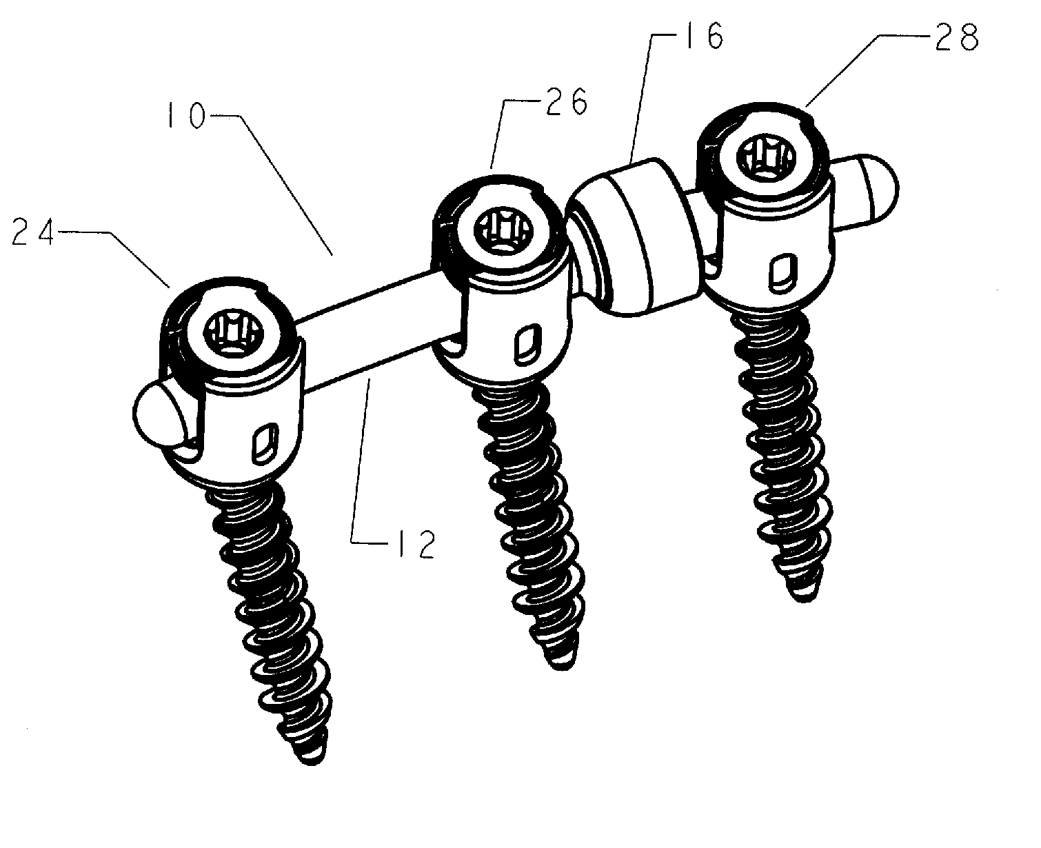
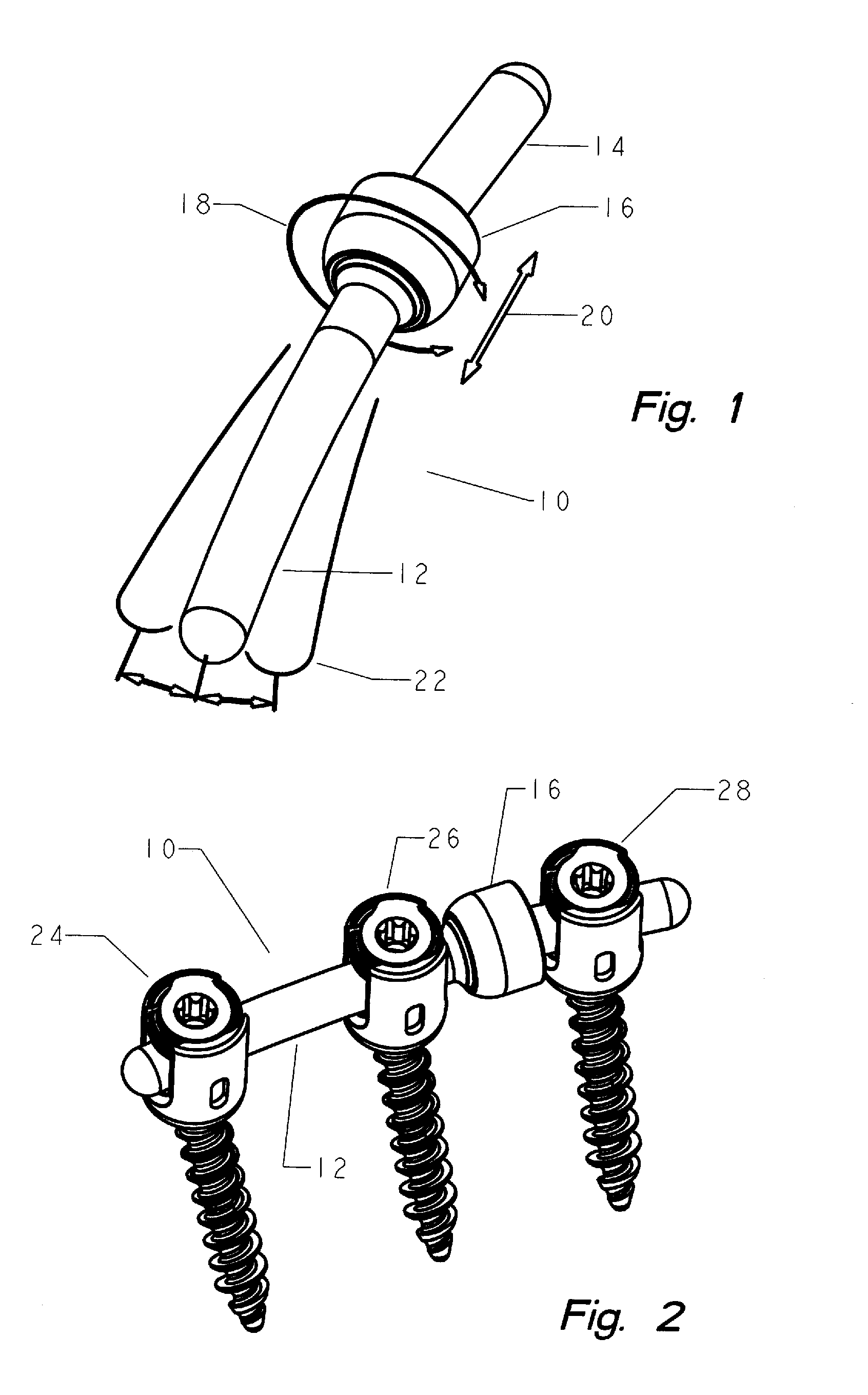
[0040]Now referring to the Figures in general and FIG. 1 in particular, depicted is the dynamic rod (10) illustrating a range of motion wherein a first rod (12) is coupled to a second rod (14) by use of the union (16). The union preferably allows a 360° range of motion (18) as well as longitudinal compression, and distraction (20). Angular deflection is infinite within a predetermined conical range depicted by (22). FIG. 2 depicts a dynamic rod (10) in a two level construct wherein a solid rod is shown between pedicle screws (24, 26) being the lower portion of the first end (12) with the union (16) depicted between the second pedicle screw (26) and a third pedicle screw (28).

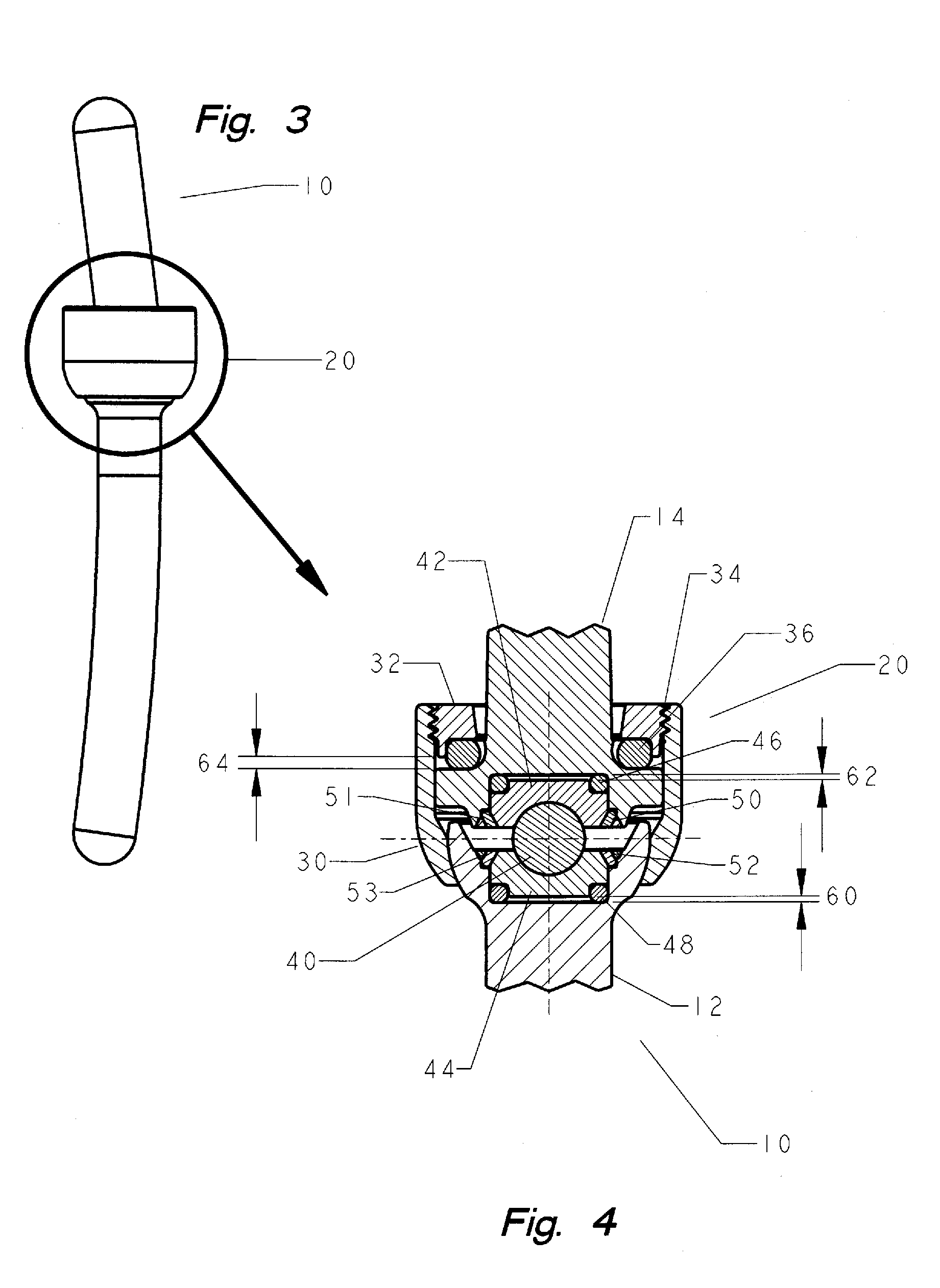
[0041]FIG. 3 depicts the dynamic rod (10) with a cross sectional portion of the union (20) as set forth in FIG. 4. FIG. 4 is a cross sectional view of the dynamic rod (10) and in particular the union (20). The first rod (12) is connected to the second rod (14) wherein a cap nut (30) is shown threadably engaged w...


PUM


Abstract

Disclosed is a dynamic rod assembly for intervertebral stabilization that allows for load sharing across vertebrae by providing predetermined compression, distraction and bending. The dynamic rod is based on a first and second rod having a flexible union. The flexible union includes a retaining element for securing the rods in position and a bearing element interposed between a first and second bearing seat permitting the compression, distraction and bending.

Description

RELATED PATENTS[0001]This invention claims the priority date of provisional patent application No. 60 / 867,333 filed Nov. 27, 2006 the contents of which is incorporated herein by reference.FIELD OF THE INVENTION[0002]This invention is related to cervical spine surgery and in particular to a dynamic rod used for posterior pedicle fixation.BACKGROUND OF THE INVENTION[0003]The most common type of posterior pedicle fixation for vertebral bodies within a human spine is performed by use of pedicle screws, hooks and the like which are attached to vertebrae and then secured together with rods or plates for immobilization and stabilization of the vertebral bodies. Such systems are generally rigid and do not accommodate load sharing across multiple spinal vertebrae occurring through either physical activity or attribute of the individual or characteristics due to aging.[0004]Spinal fixation, such as lumbar sacral fusion and the correction of spinal deformities such as scoliotic curves, is a we...

Claims


Application Information

Patent Timeline
Patent Type & Authority Applications(United States)
IPC IPC(8): A61B17/58A61B17/08
CPCA61B17/7004A61B17/7011A61B17/7026A61B17/7025A61B17/7023
Inventor DOUBLER, ROBERT L.HAMMILL, JOHN E.
Owner DOUBLER ROBERT L
Why Eureka
Try Eureka