
Multi-stage load distributing apparatus and method, and program

a load distribution and multi-stage technology, applied in the field of multi-stage load distribution apparatus, method and program, can solve the problem that the distribution apparatus itself constitutes a communication bottleneck

Inactive Publication Date: 2006-09-21
FUJITSU LTD
View PDF4 Cites 30 Cited by
  • Summary
  • Abstract
  • Description
  • Claims
  • Application Information

AI Technical Summary

Benefits of technology

[0032] Incidentally, details of the multi-stage load distributing method of the present invention are basically the same as the multi-stage load distributing apparatus of the present invention. According to the present invention, since the preceding stage load distributing apparatus always acquires server information from the latter stage load distributing apparatus to recognize such a status as high load of a server or failure thereof and always calculates a distribution ratio to the severs functioning normally to distribute a request from a client to the latter stage loading distributing apparatuses, such an event is securely prevented from occurring that load is concentrated on a specific server or communication is made impossible by distributing a request from a client to a server broken down, and statuses of servers positioned on an end side can be recognized substantially in real time, so that load distribution optimized to be suitable for server status can be dynamically conducted. In case of a standard protocol such as HTTP, the preceding stage load distributing apparatus extracts an server IP address embedded in a header of a client response packet from a server from the latter stage load distributing apparatus, so that sever information can be acquired simply and securely. When server information can not be embedded in a client response packet due to encryption of SSL or the like, notification is obtained by requiring server information from the preceding stage load distributing apparatus to the latter stage load distributing apparatus, so that sever information can be acquired simply and securely. Further, the first mode is set in an ordinary status, and the preceding stage load distributing apparatus extracts a sever IP address embedded in a header of a client response packet from a server from the latter stage load distributing apparatus. However, when the client response packet can not be received at a calculating time for a distribution ratio due to a temporary slow-down of the latter stage load distributing apparatus or the server or when a request frequency from a client is low, the second mode is set and notification is obtained by requiring server information from the preceding stage load distributing apparatus to the latter stage load distributing apparatus, so that sever information can be securely acquired and an optimal load distribution corresponding to server status at that time can be dynamically realized. The above and other objects, features, and advantages of the present invention will become more apparent from the following detailed description with reference to the drawings.

Problems solved by technology

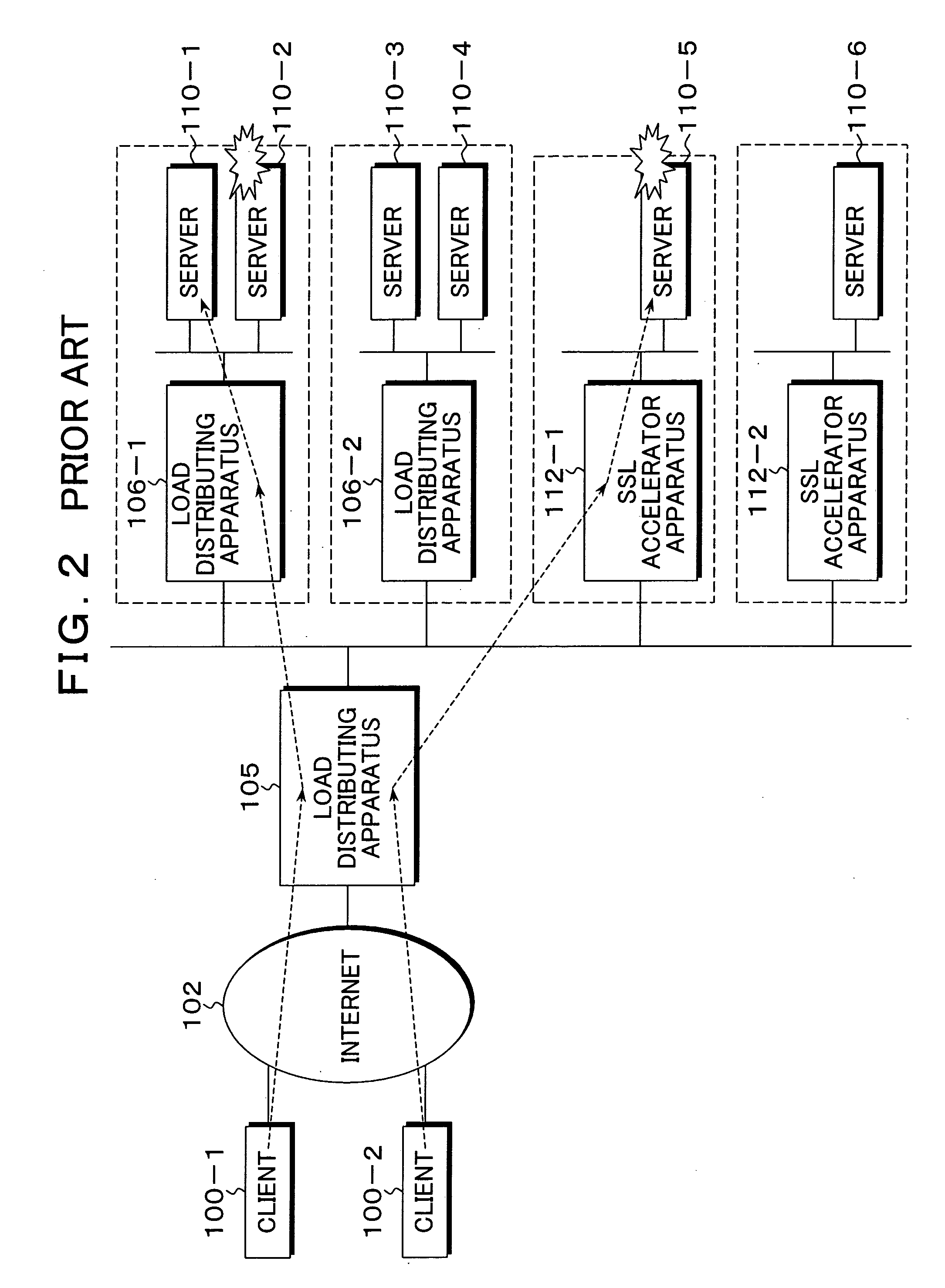
As a result, when server load distribution is performed while using these functions, load on the load distributing apparatus itself increases, so that such a problem occurs that the load distributing apparatus itself constitutes a communication bottleneck.

Method used


Image

  • Multi-stage load distributing apparatus and method, and program
  • Multi-stage load distributing apparatus and method, and program
  • Multi-stage load distributing apparatus and method, and program

Examples


Embodiment Construction

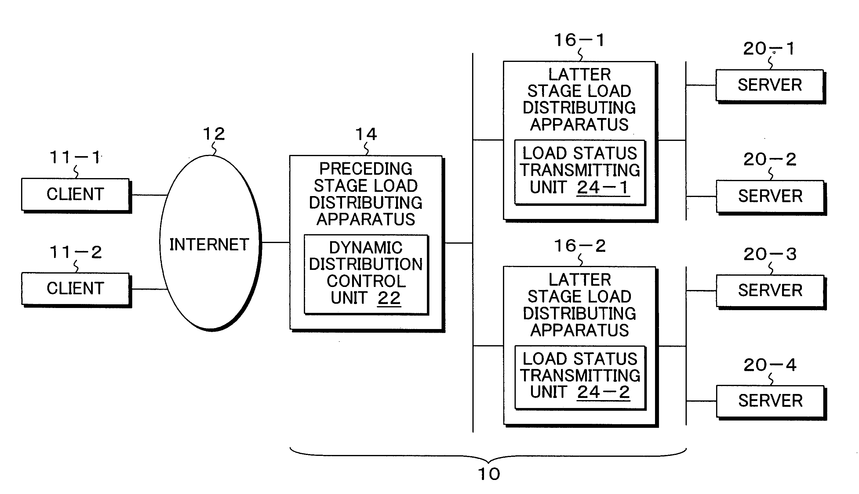
[0056]FIG. 3 is a block diagram of a multi-stage load distributing apparatus of the present invention taking a system configuration of an information notifying type. In FIG. 3, a multi-stage load distributing apparatus 10 of the present invention is constituted of a preceding stage load distributing apparatus 14, and a latter stage load distributing apparatuses 16-1, 16-2. The multi-stage load distributing apparatus 10 is connected with clients 11-1, 11-2 via Internet 12, the latter stage load distributing apparatus 16-1 is connected with severs 20-1, 20-2 serving as end servers, and the latter stage load distributing apparatus 16-2 is connected with servers 20-3, 20-4 serving as end servers. In such a multi-stage load distributing apparatus 10 according the present invention, for example, the client 11-1 issues a request to ┌http: / / www.a.com┘ and, for example, an IP address [10.10.1.100], for example, defining the preceding stage load distributing apparatus 13 as a virtual server i...


PUM


Abstract

A multi-stage load distributing apparatus is constituted of a preceding stage load distributing apparatus connected to a network, a plurality of latter stage load distributing apparatuses connected to the preceding load distributing apparatus, and one or plural servers connected to each latter stage load distributing apparatus, where, after a request from a client is distributed from the preceding stage load distributing apparatus to either of the latter stage load distributing apparatuses, the request is distributed to either of the servers. The latter stage load distributing apparatus is provided with a load status transmitting unit that transmits a status of the server connected itself to the preceding stage load distributing apparatus, and the preceding stage load distributing apparatus is provided with a dynamic distribution control unit that determines a status of the server based upon transmission information from the load status transmitting unit of the latter stage load distributing apparatus to perform allocation control on a request from the client.

Description

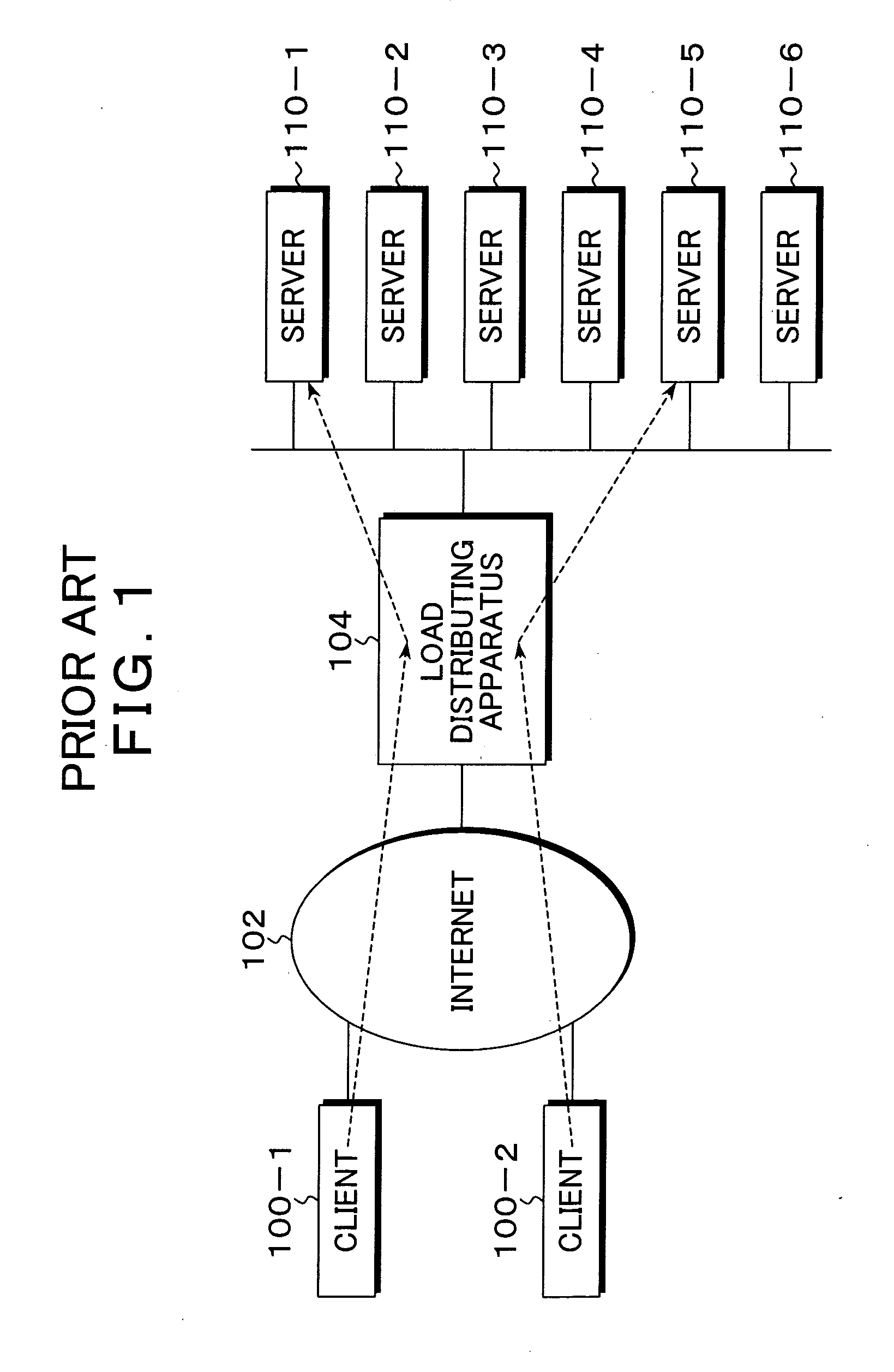
[0001] This application is a priority based on prior application No. JP 2005-41687, filed Feb. 18, 2005, in Japan. BACKGROUND OF THE INVENTION [0002] 1. Field of the Invention [0003] The present invention relates to a multi-stage load distributing apparatus, method and program that uses a plurality of load distributing apparatuses arranged in a multi-stage of a preceding stage and a latter stage to cause servers to perform distribution processing of a processing request from a client, and in particular to a multi-stage load distributing apparatus, method and program that dynamically performs load distribution of a multi-stage according to working status of serves. [0004] 2. Description of the Related Arts [0005] Conventionally, as a load distribution (load balance) of servers in a server client system utilizing Internet, for example, there is one shown in FIG. 1. In the server load distribution shown in FIG. 1, it is a common practice that a load distributing apparatus 104 is dispos...

Claims


Application Information

Patent Timeline
Patent Type & Authority Applications(United States)
IPC IPC(8): G06F15/173
CPCH04L67/1008H04L69/16H04L67/02H04L67/1002H04L69/22H04L69/161H04L67/1001
Inventor SHIMADA, YUUSUKE
Owner FUJITSU LTD
Learn More