Card reader

a card reader and card reader technology, applied in the field of card readers, can solve problems such as data in the medium or the medium being broken, and achieve the effect of preventing data in the medium or the medium from being broken

Inactive Publication Date: 2006-01-24
FUJIFILM HLDG CORP +1
View PDF14 Cites 8 Cited by
  • Summary
  • Abstract
  • Description
  • Claims
  • Application Information

AI Technical Summary

Benefits of technology

[0006]The present invention is made to solve the above problem and its object is to provide a card reader capable of preventing the data in a medium or the medium from being broken due to hot plug of the medium from the card reader.
[0009]Moreover, the second aspect of the present invention is constituted so that the moving member prevents the medium from being removed by holding a corner portion or one side of the medium in the first aspect.
[0010]According to the above configuration, even for a small card reader having a simple configuration, a medium is securely held by a moving member and hot plug of the medium from the card reader is prevented.
[0014]According to the above configuration, hot plug of a medium is securely prevented because power is supplied to the medium when the medium is locked but power is not supplied to the medium when medium lock is cancelled.
[0017]According to the present invention, it is possible to prevent the data in a medium or the medium from being broken due to hot plug of the medium from a card reader.

Problems solved by technology

Therefore, a problem occurs that the data in the medium or the medium is broken due to the hot plug of the medium.

Method used


Image

  • Card reader
  • Card reader
  • Card reader

Examples


first embodiment

(First Embodiment)

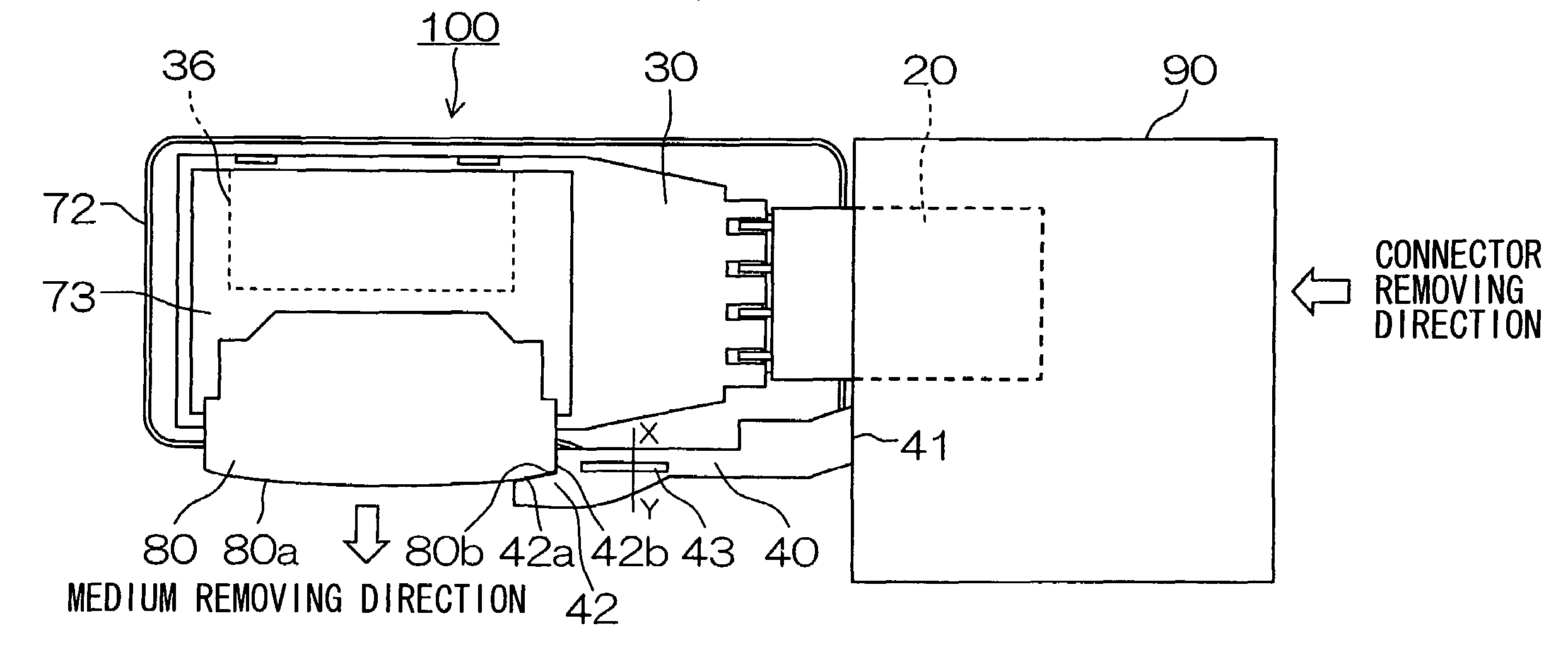
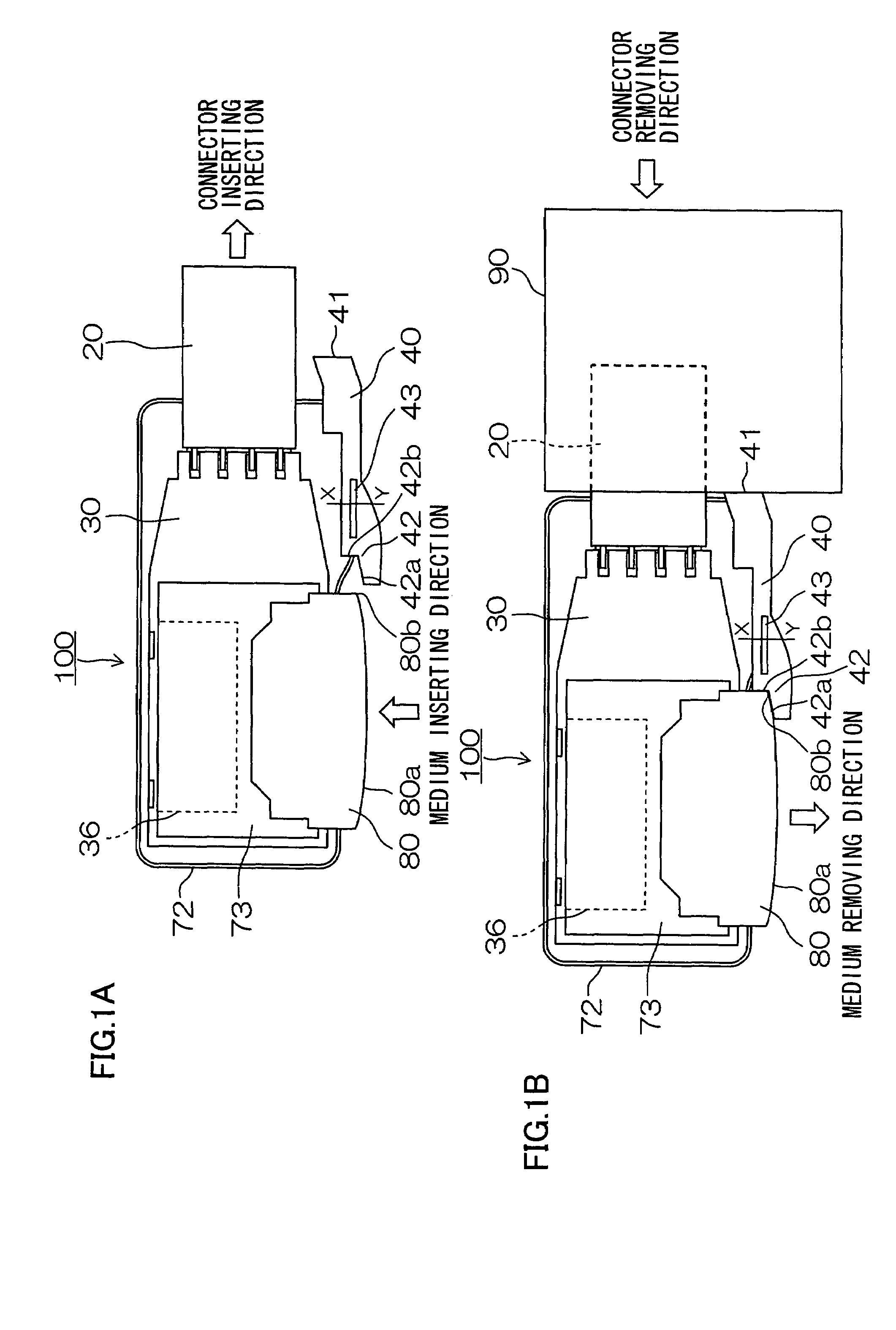
[0026]FIGS. 1A and 1B are top views showing the card reader 100 of the first embodiment of the present invention. In the case of the card reader 100, a card-like medium 80 which stores data such as image data is removable. Moreover, the card reader 100 is removable from an electronic equipment 90 such as a personal computer. FIG. 1A shows a state in which the card reader 100 is not set to the electronic equipment 90 and FIG. 1B shows a state in which the card reader 100 is set to the electronic equipment 90. In the state in which the card reader 100 is set to the electronic equipment 90 shown in FIG. 1B, the card reader 100 and electronic equipment 90 are connected by a USB (Universal Serial Bus). FIGS. 1A and 1B show states in which a first cover to be connected with a second cover 72 is removed and the second cover 72 is left for explanation. In fact, however, not-illustrated first cover and second cover 72 are mutually connected.

[0027]A part of a USB connector 2...

second embodiment

(Second Embodiment)

[0038]FIGS. 3A and 3B are top views showing a card reader 200 of second embodiment of the present invention. FIG. 3A shows a state in which the card reader 200 is not set to the electronic equipment 90 and FIG. 3B shows a state in which the card reader 200 is set the electronic equipment 90. A portion common to the portion of the card reader 100 of the first embodiment shown in FIG. 1 is provided with the same symbol and its detailed description is omitted.

[0039]An urging member 46 urges the locking key 40 in the direction separating the locking key 40 from the medium 80 (that is, inserting direction of the USB connector 20). When the USB connector 20 is removed from the housing of the electronic equipment 90, the locking key 40 is moved in the direction separating from the medium 80 (inserting direction of the USB connector 20) due to urging by the urging member 46 and the medium 80 held by the holding claw 42 of the locking key 40 is released.

[0040]As shown by a...

third embodiment

(Third Embodiment)

[0052]FIGS. 7A and 7B are top views showing a card reader 300 of the third embodiment of the present invention. FIG. 7A shows a state in which the card reader 300 is not set to the electronic equipment 90 and FIG. 7B shows a state in which the card reader 300 is set to the electronic equipment 90. A portion common to the portion of the card reader 100 of the first embodiment shown in FIG. 1 is provided with the same symbol and its detailed description is omitted.

[0053]The card reader 300 of the third embodiment is different from the card reader of the first embodiment in that the locking key 40 entirely covers one side 80a of the medium 80 when the USB connector 20 is inserted into the housing of the electronic equipment 90. One side 80a covered with the locking key 40 is flat and the opposing face 42c of the locking key 40 is also formed to be flat.

[0054]Moreover, though the urging member 46 and medium lock detecting portion 50 shown in FIG. 3 are omitted in FIG. ...


PUM


Abstract

The housing of a card reader has a connector to be inserted into an electronic equipment. When using a moving member movable in the inserting and removing directions (inserting direction and removing direction) of the connector and inserting the connector into the housing of the electronic equipment, the moving member is pushed by the circumferential portion of the counterpart connector of the electronic equipment connecting to the connector and moved in the removing direction of the connector to prevent a medium from being removed.

Description

BACKGROUND OF THE INVENTION[0001]1. Field of the Invention[0002]The present invention relates to a card reader, particularly to a card reader whose housing has a connector to be electrically connected with an electronic equipment such as a personal computer.[0003]2. Description of the Related Art[0004]A card reader is conventionally known which is obtained by constituting a USB (Universal Serial Bus) connector to be inserted into an electronic equipment such as a personal computer, a medium housing portion into which a medium such as a memory card is inserted, and a circuit which transfers the data stored in the medium to an electronic equipment by one housing. Moreover, a card reader is proposed which is obtained by fitting a USB connector into a circular axis case so that the USB connector can be rotated (Japanese Utility Model Registration No. 3080713).SUMMARY OF THE INVENTION[0005]In the case of a conventional card reader, when a medium is removed from the card reader during an ...

Claims


Application Information

Patent Timeline
Patent Type & Authority Patents(United States)
IPC IPC(8): G06K7/06G06F1/18G06K7/00G06K13/08G06K17/00
CPCG06K7/0047G06K19/07741G06K13/085G06K13/08G06K17/00
Inventor FUKUDA, OSAMU
Owner FUJIFILM HLDG CORP
Why Eureka
Try Eureka