Rod contouring alignment linkage

a technology of alignment linkage and alignment ring, which is applied in the field of selection and configuration of implantable devices, can solve the problems of high equipment cost, added complexity, and loss of most of the beneficial effects of misimplantation procedur

Active Publication Date: 2008-05-29
STRYKER EURO OPERATIONS HLDG LLC
View PDF27 Cites 54 Cited by
  • Summary
  • Abstract
  • Description
  • Claims
  • Application Information

AI Technical Summary

Benefits of technology

[0007]The present invention fills the need described above by providing a systems and methods for configuring and/or selecting implantable devices for posterior spinal fusion. The system includes pedicle screws designed to provide polyaxial coupling to pedicles of a vertebra. Pedicle screws have a cage shaped to receive a rod, and a screw that is able to extend from the cage

Problems solved by technology

However, such equipment is expensive and constitutes an added layer of complexity in the operating room.
Unfortunately, if a larger incision must be m

Method used


Image

  • Rod contouring alignment linkage
  • Rod contouring alignment linkage
  • Rod contouring alignment linkage

Examples


Embodiment Construction

[0039]The present invention relates to systems and methods for configuring and / or selecting devices to be implanted in the body. More particularly, the present invention relates to projecting anatomic points located within a patient's body outside the patient's body to facilitate selection or configuration of an implant that is to be implanted in the body between the anatomic points. Although the examples provided herein generally relate to contouring a rod for a posterior spinal fusion system, the present invention may be applied to any procedure in which the relative position and / or orientations of internal anatomic locations are to be measured or used to configure or select an implant.

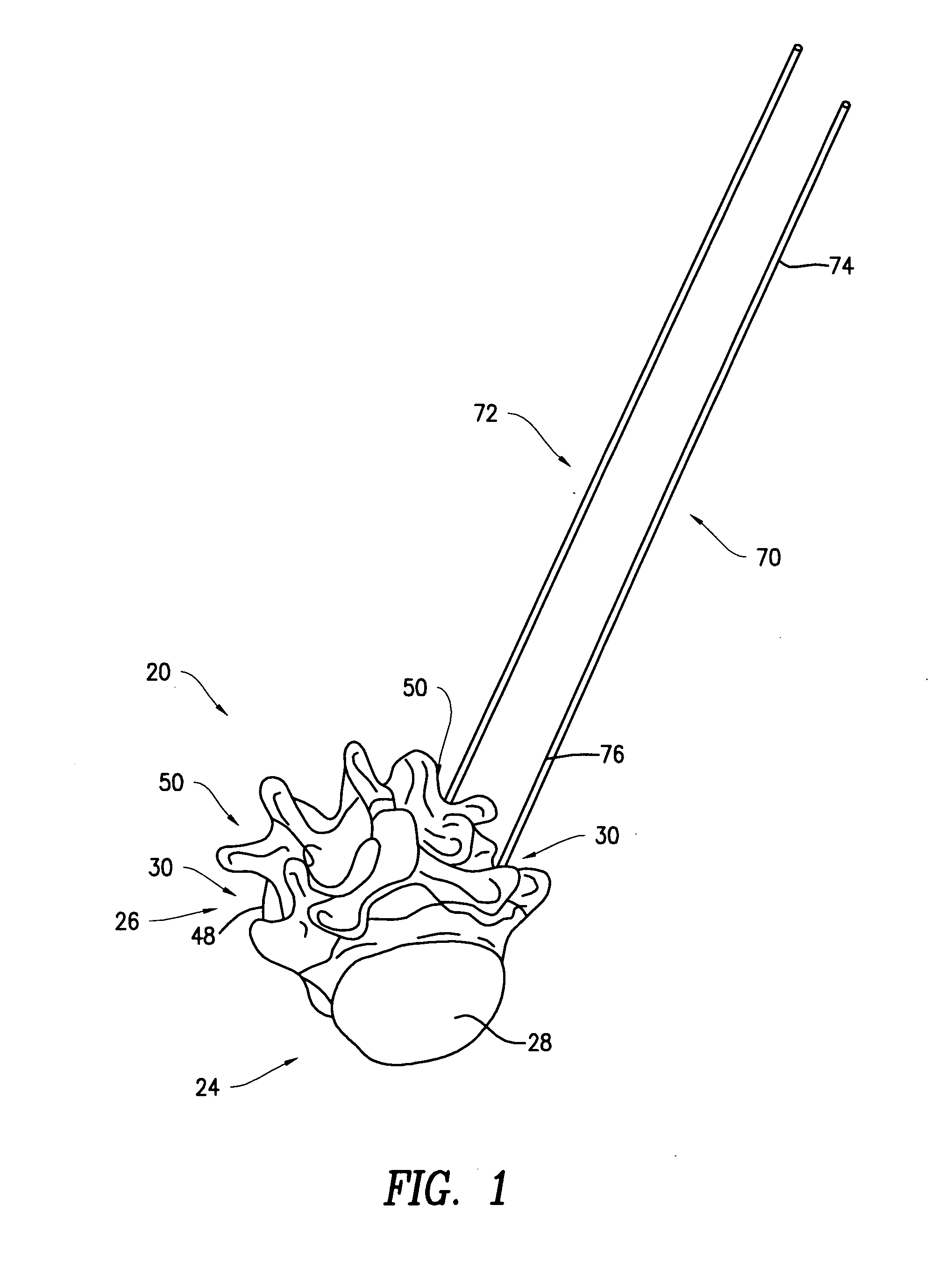
[0040]Referring to FIG. 1, a perspective view illustrates a portion of a spine 20. As shown, the portion of the spine 20 illustrated in FIG. 1 includes a first vertebra 24, which may be the L5 (Fifth Lumbar) vertebra of a patient, and a second vertebra 26, which may be the L4 (Fourth Lumbar) vertebr...


PUM


Abstract

Pedicle screws are designed to provide polyaxial coupling to pedicles of a vertebra. Intermediate pieces are attached to the pedicles screws and receive extender shafts. Extenders are inserted in the intermediate piece. The extenders project the anatomic points located in the cage outside the patient's body to facilitate proper contouring of a rod. An alignment linkage is used to ensure that the extenders are parallel to each other. The alignment linkage includes a linkage frame, an articulating linkage and a locking member. The articulating linkage has all rotational degrees of freedom and thereby adapts to any varying trajectories of the extenders and distance between the extenders. The alignment linkage includes a locking member with a pop-up indicator. The pop-up indicator notifies the users when the locking member is tightened with two of the extenders in non-parallel configuration.

Description

CROSS-REFERENCE TO RELATED APPLICATIONS[0001]The present application claims priority from Provisional Application No. 60 / 847,157, filed Sep. 25, 2006, the disclosure of which is hereby incorporated herein by reference.BACKGROUND OF THE INVENTION[0002]1. Field of the Invention[0003]The present invention relates generally to the selection and configuration of implantable devices, and more particularly to alignment linkage for orthopedic implant configuration for posterior spinal fusion systems.[0004]2. Brief Description of the Prior Art[0005]A wide variety of orthopedic implants exist. Such implants are typically anchored to bones within the body. Every person has different bone structure; accordingly, implants must vary considerably in geometry to meet the needs of a broad range of patients. Sophisticated surgical navigation equipment may be used to properly locate these implants on the bone. However, such equipment is expensive and constitutes an added layer of complexity in the ope...

Claims


Application Information

Patent Timeline
IPC IPC(8): A61B17/56A61B17/58
CPCA61B17/7002A61B17/8863A61B17/708A61B17/7037A61B90/06A61B2090/061A61B17/86A61B17/7074
Inventor ARNETT, JEFFERYBUTTERS, JOSHUA A.
Owner STRYKER EURO OPERATIONS HLDG LLC
Why Eureka
Try Eureka