Security window insert assembly

a technology for window inserts and components, applied in the field of security windows, can solve problems such as inability to be removed

a technology for window inserts and components, applied in the field of security windows, can solve problems such as inability to be removed

US20080127581A1Inactive Publication Date: 2008-06-05WALTERS NICK

Image

  • Security window insert assembly
  • Security window insert assembly
  • Security window insert assembly

Examples


Embodiment Construction

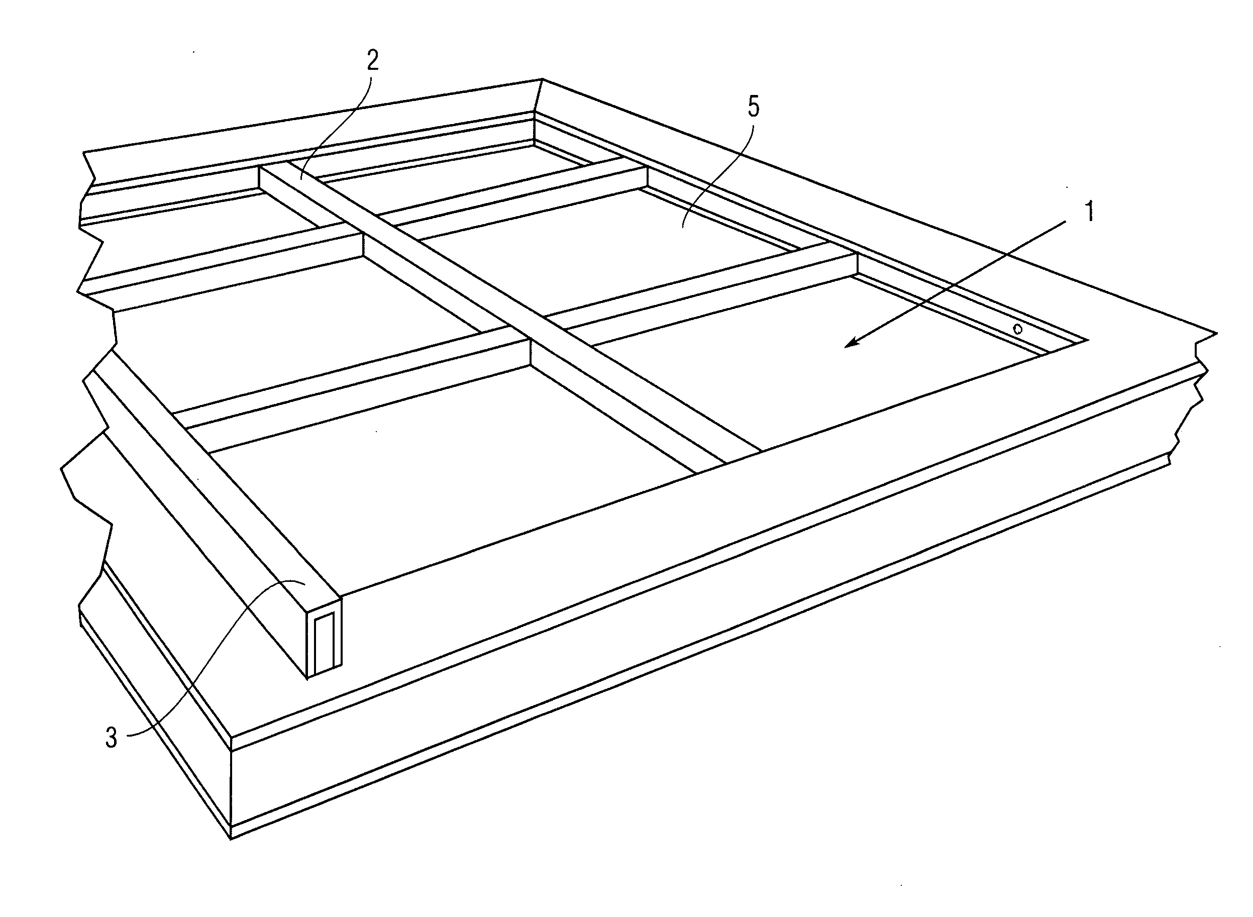
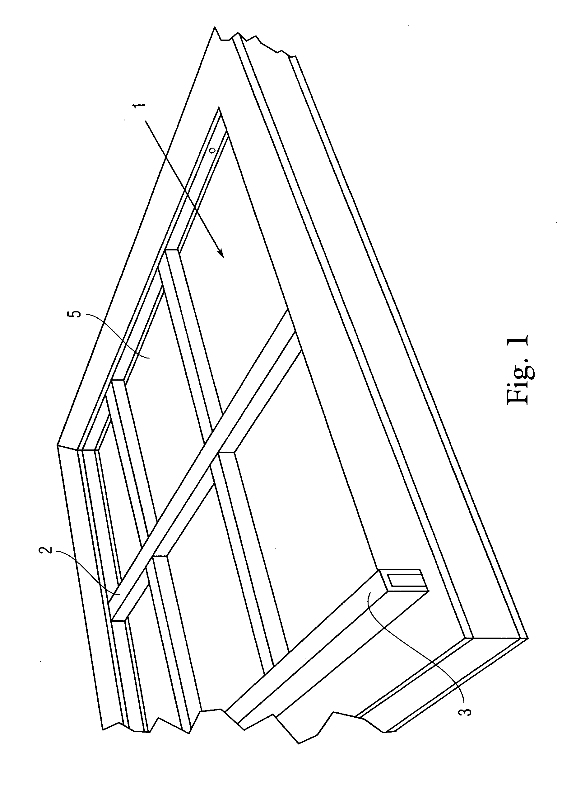
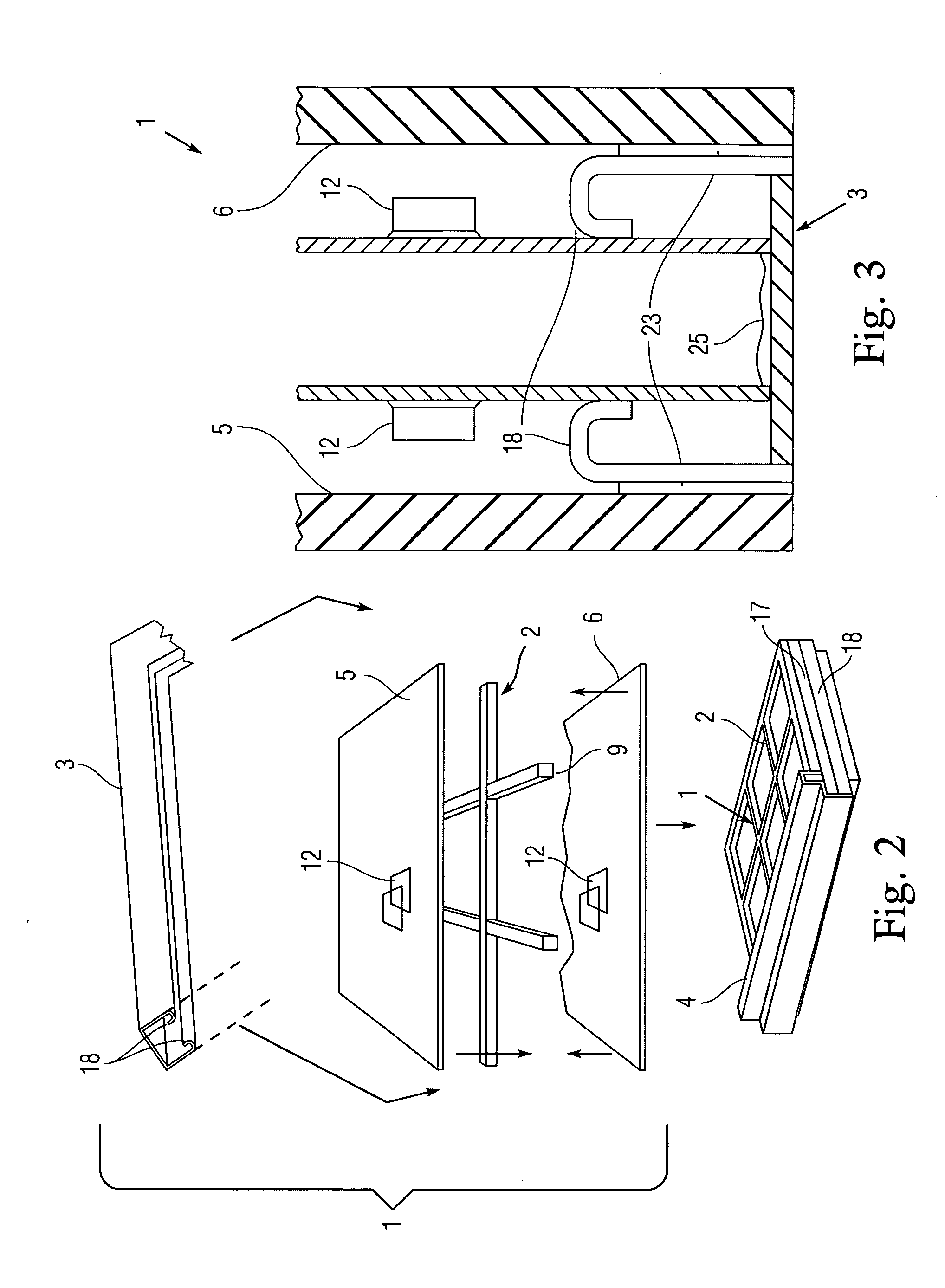
[0021]The present invention is a security window insert assembly 1 retrofit to existing insulated window. FIGS. 1-4 are a perspective view, assembly drawing, side cross-section, and top perspective view, respectively, of the security window insert assembly 1 described in the context of a double pane window. The assembly 1 generally comprises a tubular metal grating 2 anchored within a rectangular spacer 3 and suspended between the panes 5, 6 of a double-pane window. With the tubular metal grating 2 inserted into the spacer 3 and seated between the inwardly furled interior edges 18, the panes 5, 6 of glass 5, 6 are then adhered to the outside edges of rectangular spacer 3, preferably with Butyl-rubber seals 23 there between to avoid condensation in the inner airspace. The assembly 1 can fit to any conventional detachable rectangular double pane (or multi-pane) window (here illustrated with double-panes 5, 6). As seen in FIGS. 1 and 2 (bottom inset of FIG. 2) the assembly 1 can then b...


PUM


Abstract

The present invention is a security window insert assembly retrofit to existing insulated windows (double or other multi-pane windows). The assembly generally comprises a tubular steel gridwork anchored in a substantially rectangular spacer, and opposing panes of glass adhered to the sides of the spacer such that the gridwork occupies and is suspended in the airspace between the panes of glass. The tubular gridwork comprises a gridwork of or more horizontal and one or more vertical struts leading to distal ends press-fit into the spacer. The result is a double pane window unit that may be installed within a window frame in a conventional manner. However, the security grating erects an impenetrable shield between the interior surfaces of the panes, and since it remains anchored in the spacers it cannot be removed.

Description

CROSS-REFERENCE TO RELATED APPLICATION(S)[0001]The present application derives priority from U.S. provisional application No. 60 / 841,613 filed 29 Aug. 2006.BACKGROUND OF THE INVENTION[0002]1. Field of the Invention[0003]The present invention generally relates to security windows, and more particularly to a security window insert assembly for existing double pane windows.[0004]2. Description of the Background[0005]Standard single-pane windows have minimal insulating value. Consequently, to improve a window's energy efficiency it is typical to increase the number of glass panes in the unit. Today most “insulated windows” are double- or triple-pane windows with insulating air- or gas-filled spaces between each pane. Each pane of glass and the air spaces resist heat flow. The ideal width of air spaces is between ½ and ⅝ inches. The width of the air spaces between the panes is important because air spaces that are too wide (more than ⅝ inch or 1.6 centimeters) or too narrow (less than ½ ...

Claims


Application Information

Patent Timeline
05 Jun 2008
Publication
US20080127581A1
IPC
E06B3/988
CPC
E06B5/11; E06B3/6604
Inventors
WALTERS, NICK