Height Adjustment Device For Saddles Or Handlebars

Active Publication Date: 2008-06-05
MORELLI ANGELO PONTENURE
View PDF3 Cites 16 Cited by
  • Summary
  • Abstract
  • Description
  • Claims
  • Application Information

AI Technical Summary

Benefits of technology

[0010]An object of the present invention is therefore to provide a bicycle saddle or handlebar height adjustment device which enables their precise height adjustment to be effected while mounted on the bicycle without interrupting the exercise, i.e. without having to stop, in particular during competitions.
[0011]A further object of the present invention is to provide a device which enables the saddle or handlebar height to be adjusted in a simple, quick and precise manner, without having to memorize the original position of the tube sleeve.

Problems solved by technology

In this respect, once the screw has been slackened, the tubular element supporting the saddle tends to slide downwards within the tube and the position at which the saddle was originally fixed is lost.
Moreover, if a user wishes to slightly lower or raise the saddle because of lack of comfort or ineffectiveness during pedaling, the user has necessarily to stop and carry out a difficult adjustment operation requiring considerable time, repeated measurements and various tries before the required seating improvement is achieved.
This operation is also very complex because the user should mark the initial position on the tubular element and then proceed to fine saddle height adjustment.
All this is incompatible with current cyclist requirements, particularly during competitions.
Cyclists, particularly racing cyclists, are currently not in a condition to make sophisticated saddle adjustments (corrections) during a race.
Adjusting the saddle would in fact require them to stop and lose considerable time, so compromising the result of the race.

Method used


Image

  • Height Adjustment Device For Saddles Or Handlebars
  • Height Adjustment Device For Saddles Or Handlebars
  • Height Adjustment Device For Saddles Or Handlebars

Examples


Embodiment Construction

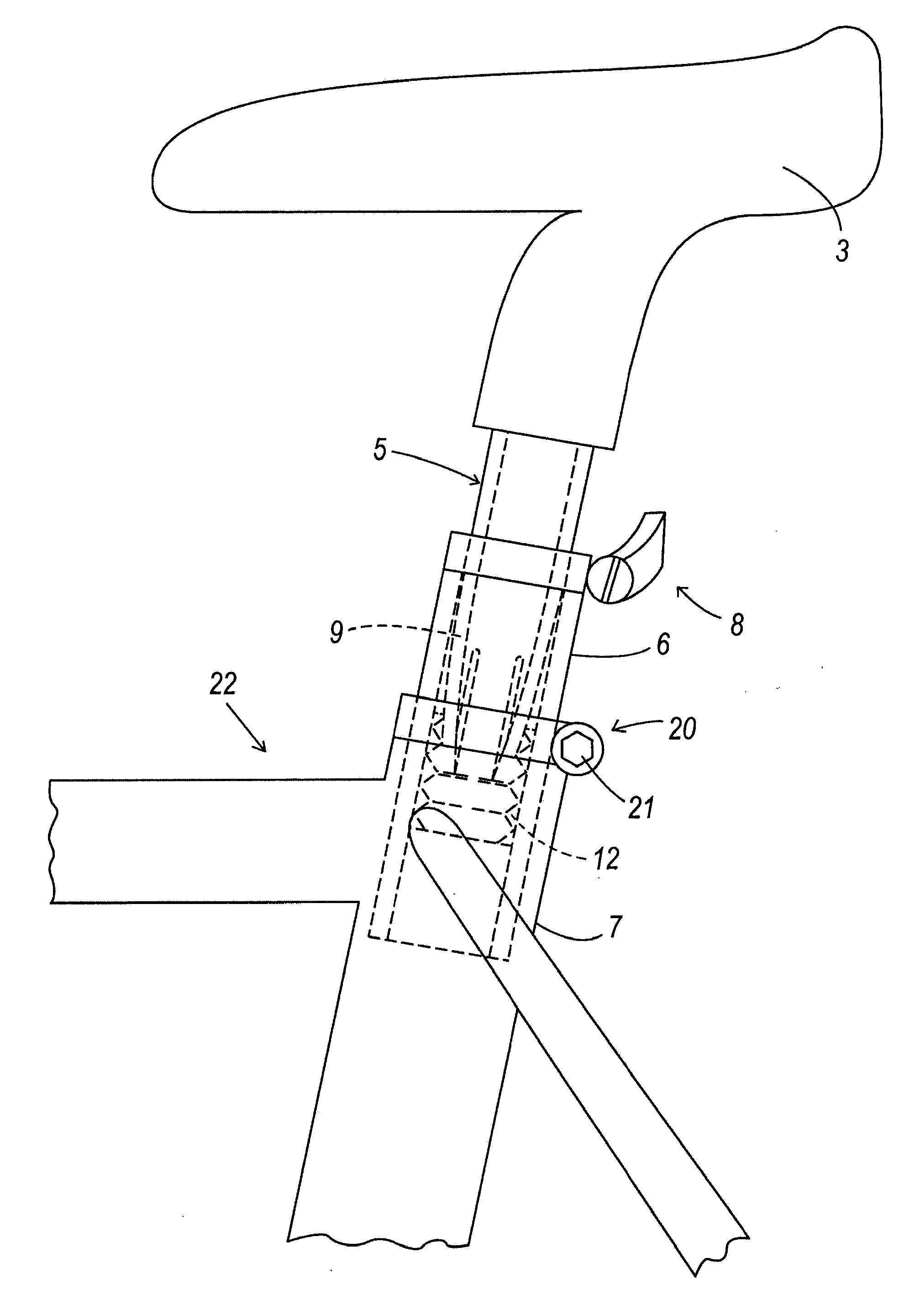
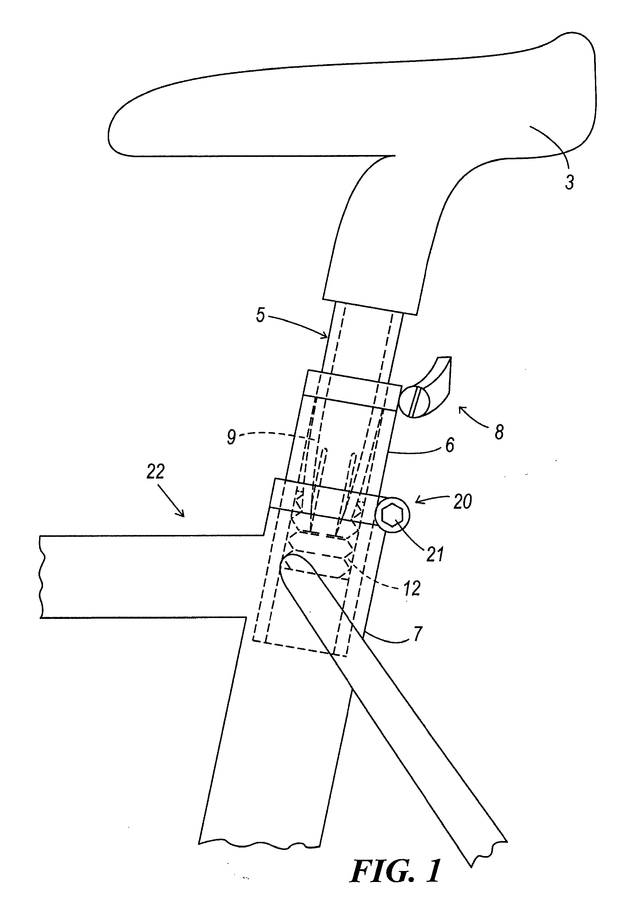
[0027]The adjustment device comprises a support element which in this embodiment is a tube sleeve 6, conventionally fixed into a frame 7 of a bicycle 22. The tube sleeve 6 is locked to the frame by a locking nut 21. A portion 4 of a tubular element 5 fixed to a saddle 3 is inserted into the tube sleeve 6. More in particular a portion 2 of the tubular element 5 having forcedly penetrated into an appropriate seat 3A provided for fixing the saddle 3.

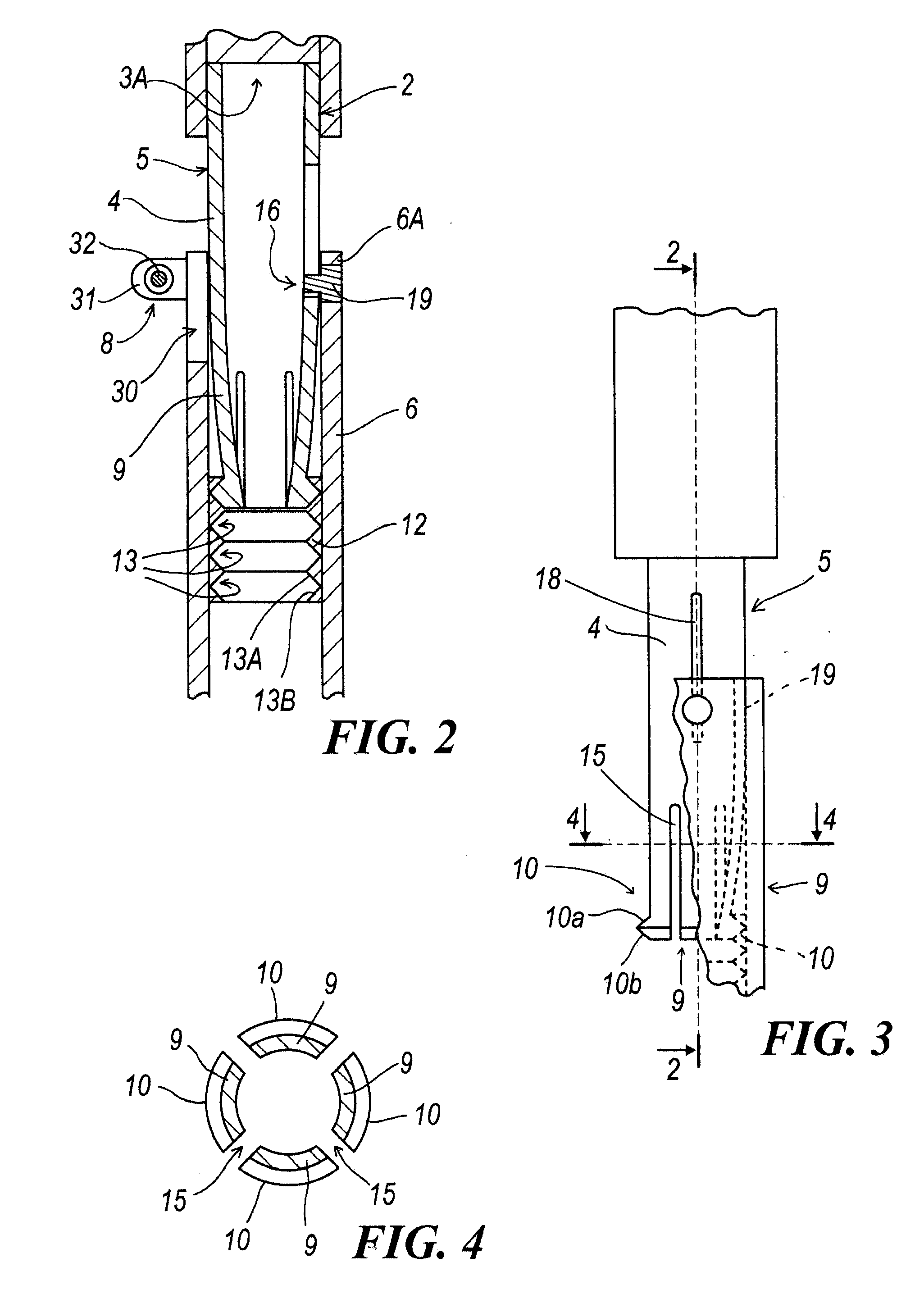
[0028]In the tubular element 5 an elongate slot 18 is provided into which a dowel 19 fixed to the tube sleeve 6 is inserted. Said dowel 19 acts as a guide to prevent the tubular element 5 from withdrawing; the dowel 19 and slot 18 also prevent the tubular element 5 from rotating relative to the tube sleeve 6 while allowing limited axial movement.

[0029]In the embodiment the tubular element 5 presents four axial grooves 15 extending from one end thereof to define four blades 9, on each of which a tooth 10 is integrally provided. Each tooth 10...


PUM


Abstract

A bicycle saddle and handlebar height adjustment device comprising a tubular element (5) provided with means (2) for its connection to said saddle (3) and presenting a portion (4) to cooperate with a support element (6, 7) for said tubular element, said support element being associated with locking means (8) for said first tubular element which maintain the tubular element (5) in a determined position relative to the support element (6, 7), in which alignment means (16) are present between said support element (6, 7) and said tubular element (5) to maintain a determined angular position between the tubular element (5) and the support element (6, 7), said locking means (8) comprising a threaded (132A) ring (132) rotatably fixed to one from among the support element (6, 7) and the tubular element (5), the other from among the support element (6, 7) and the tubular element (5) presenting a thread (5A) cooperating with the thread (132A) of said ring (132). rotation of said ring (132) causing continuous movement of one element relative to the other.

Description

FIELD OF THE INVENTION[0001]The present invention relates to a height adjustment device for bicycle saddles or handlebars in accordance with the introduction to the main claim.BACKGROUND OF THE INVENTION[0002]Bicycles comprise a frame into which a tubular element (tube sleeve) supporting a saddle and a tubular element supporting a handlebar are inserted. At the point at which the tubular element is inserted, the frame normally presents an axial slot, to the sides of which two projecting lugs are welded, with a screw passing between them. On tightening said screw, the frame diameter is slightly reduced to lock the tubular element at a determined height.[0003]The height (in particular of the saddle) is usually adjusted by slackening the screw engaging the two lugs and acting on the saddle to adjust its height by forcing it to a greater or lesser extent into the frame. Having adjusted the height, the saddle is aligned with the frame by rotating the tubular element which supports it in ...

Claims


Application Information

Patent Timeline
IPC IPC(8): B62K21/22
CPCB62J1/08Y10T74/2078Y10T74/20792B62K19/36
Inventor MORELLI, ANGELO
Owner MORELLI ANGELO PONTENURE
Why Eureka
Try Eureka