Reflection-Safe Receiver for Power Beaming

a receiver and power beam technology, applied in the field of power beam receivers, can solve the problems of power beams exceeding human exposure limits, affecting the safety of people proximate to power beams, and unsafe use of prior power beam systems around people without eye protection

Inactive Publication Date: 2008-06-05
POWERBEAM
View PDF21 Cites 22 Cited by
  • Summary
  • Abstract
  • Description
  • Claims
  • Application Information

AI Technical Summary

Problems solved by technology

Prior power beaming systems are unsafe for use around people not wearing eye protection.
A human proximate to a power beaming system can be hurt in two ways.
In a power beam system where the beam path is not protected from intrusion, a power beam exceeding human exposure limits is unsafe.
Second, a person can receive unsafe levels of light reflected from a surface in the path of the beam.
That surface might be accidentally inserted in the beam path, or it might be part of the power beaming receiver.
Even a power beaming receiver with anti-reflection coated surfaces is potentially a source of unsafe reflections because it is subject to contamination with water, oil, or other reflective material.
Power beaming systems are not currently designed to limit reflections to be within regulatory limits for huma

Method used


Image

  • Reflection-Safe Receiver for Power Beaming
  • Reflection-Safe Receiver for Power Beaming
  • Reflection-Safe Receiver for Power Beaming

Examples


Embodiment Construction

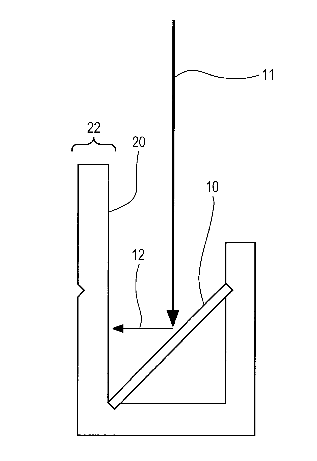
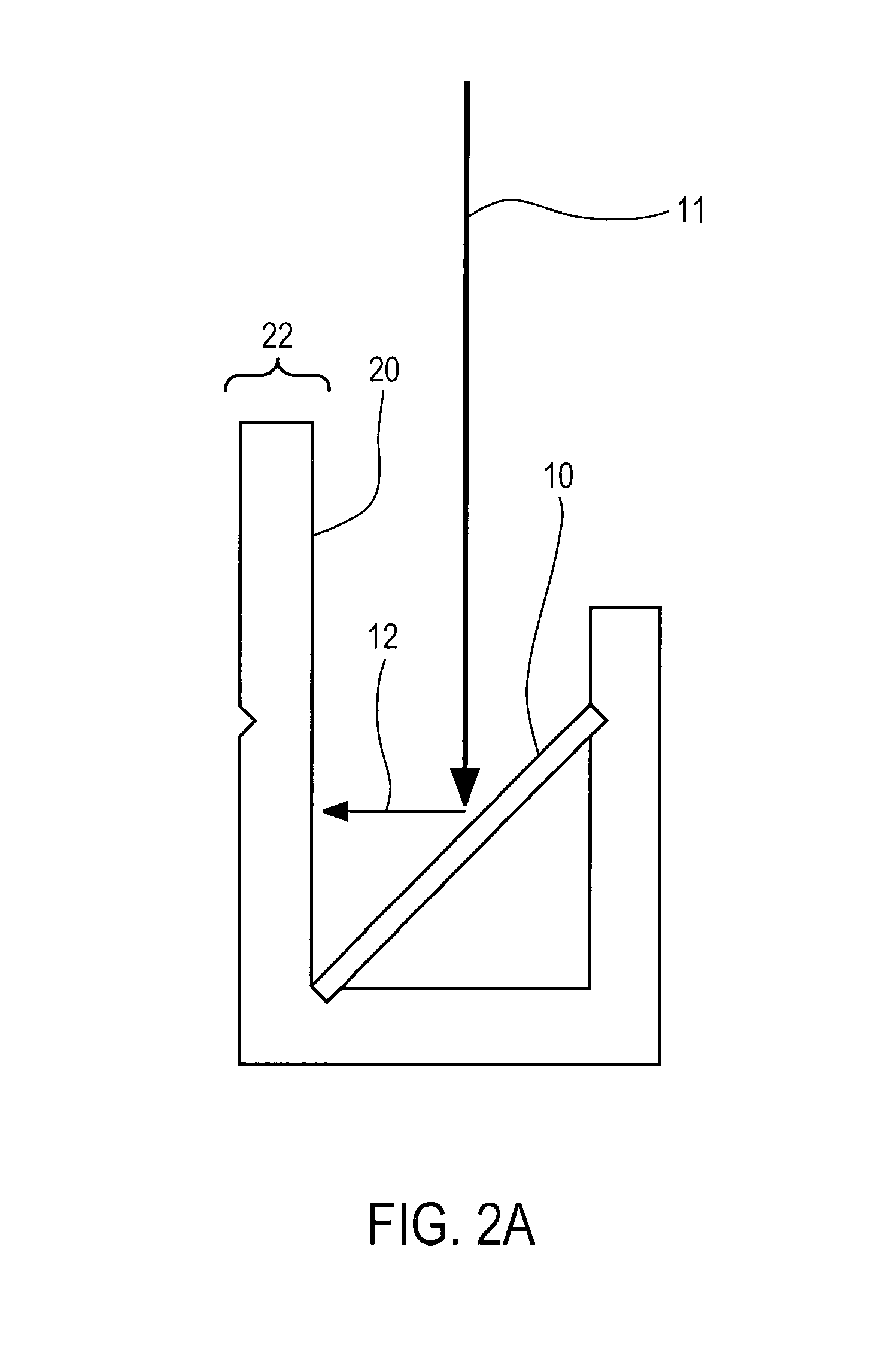
[0027]FIG. 2A is an illustration of one power conversion element 10 of a power beam receiver arranged to reflect incident light 11 into a baffle 20, in accordance with one embodiment. In this embodiment, power receiving element 10 is tilted with respect to the incoming beam 11. For illustration purposes, only a single power conversion element 10 with a single baffle is shown, but multiple power conversion elements arranged at the same or different angles with multiple baffles can be included in a power beam receiver, for example in a line or grid pattern.

[0028]For many practical power beaming systems, power receiving element 10 will be one or more photodiodes. All light reflected 12 from its surface is trapped by a baffle 20. Baffle 20 can be made of any material that overwhelmingly absorbs light at least at the wavelength at which the system operates. Example materials include black anodized aluminum or a rigid material covered in a light-absorptive cloth. In FIG. 2A, there is no l...


PUM


Abstract

Embodiments of the invention include a power beam receiver that will not reflect light beyond the regulatory limits for human exposure, except along paths known to be without people. In one embodiment, a baffle is used to trap reflections from surfaces of the receiver. In a second embodiment, the power beam receiver is arranged so that reflections are reflected to another surface of the receiver. These surfaces may be designed as a retroreflector. In a third embodiment, an intentional scattering medium is added to the power beam receiver so that parallel light rays incident on the front surface of the power beam receiver are scattered through a series of angles. As a result, any light escaping the system is diffused.

Description

CROSS REFERENCE TO RELATED APPLICATION[0001]This application claims priority under 35 U.S.C. § 119(e) to U.S. Provisional Patent Application No. 60 / 866,807 filed Nov. 21, 2006, which is hereby incorporated by reference in its entirety.BACKGROUND OF THE INVENTION[0002]1. Field of the Invention[0003]This invention relates to the receive portion of a power beam system. More specifically, it relates to a power beam receiver that limits reflection of the incident radiation for increased safety.[0004]2. Description of the Related Art[0005]Prior power beaming systems are unsafe for use around people not wearing eye protection. A human proximate to a power beaming system can be hurt in two ways. First, a person can receive power directly from the transmitter—a person could look into the beam. The reader should assume that the incident beam path is protected from intrusion. In a power beam system where the beam path is not protected from intrusion, a power beam exceeding human exposure limit...

Claims


Application Information

Patent Timeline
IPC IPC(8): G02B27/00
CPCH02J5/00H04B10/807H02J17/00H02J50/30
Inventor GRAHAM, DAVID S.
Owner POWERBEAM
Why Eureka
Try Eureka