Fault localization apparatus for optical line using subcarrier multiplexing (SCM) monitoring sgnal and method thereof

a fault localization and optical line technology, applied in the field of fault localization apparatus based on optical communication network, can solve the problems of reducing the reliability affecting the quality of the communication network, and affecting the quality of the service provided by the conventional technology

Active Publication Date: 2008-06-05
ELECTRONICS & TELECOMM RES INST
View PDF7 Cites 21 Cited by
  • Summary
  • Abstract
  • Description
  • Claims
  • Application Information

AI Technical Summary

Problems solved by technology

However, assuming that super-high-speed data services such as telecommuting, teleconferencing, services of moving pictures having as high quality as high-definition televisions (HDTVs), tele-education, and telemedicine services are generalized to common subscribers, the conventional technologies may not provide sufficiently high quality services for a broadband due to their restrictions in terms of bandwidths and distances.
Optical fibers which are transmission media of optical signals used for the optical communication network, are buried under the ground and thus may be relatively easily cut or damaged by an external impact such as a natural calamity or construction which may impact the ground, compared to copper cables which are transmission media of electrical signals.
If communication services to subscribers are discontinued due to one of the above reasons, this may reduce reliability of the communication network and may also reduces customer satisfaction.
However, the above technology requires an additional monitoring light source and an additional optical BPF for attenuation of the monitoring light source and thus has a problem from an economical aspect.
However, although the above method does not use an additional monitoring light source, the expensive tunable BPF is necessary to receive monitoring optical pulse signals.

Method used


Image

  • Fault localization apparatus for optical line using subcarrier multiplexing (SCM) monitoring sgnal and method thereof
  • Fault localization apparatus for optical line using subcarrier multiplexing (SCM) monitoring sgnal and method thereof
  • Fault localization apparatus for optical line using subcarrier multiplexing (SCM) monitoring sgnal and method thereof

Examples


Embodiment Construction

[0033]Hereinafter, the present invention will be described in detail by explaining embodiments of the invention with reference to the attached drawings. Like reference numerals in the drawings denote like elements. In the following description of the present invention, a detailed description of known functions and configurations incorporated herein will be omitted when it may make the subject matter of the present invention unclear.

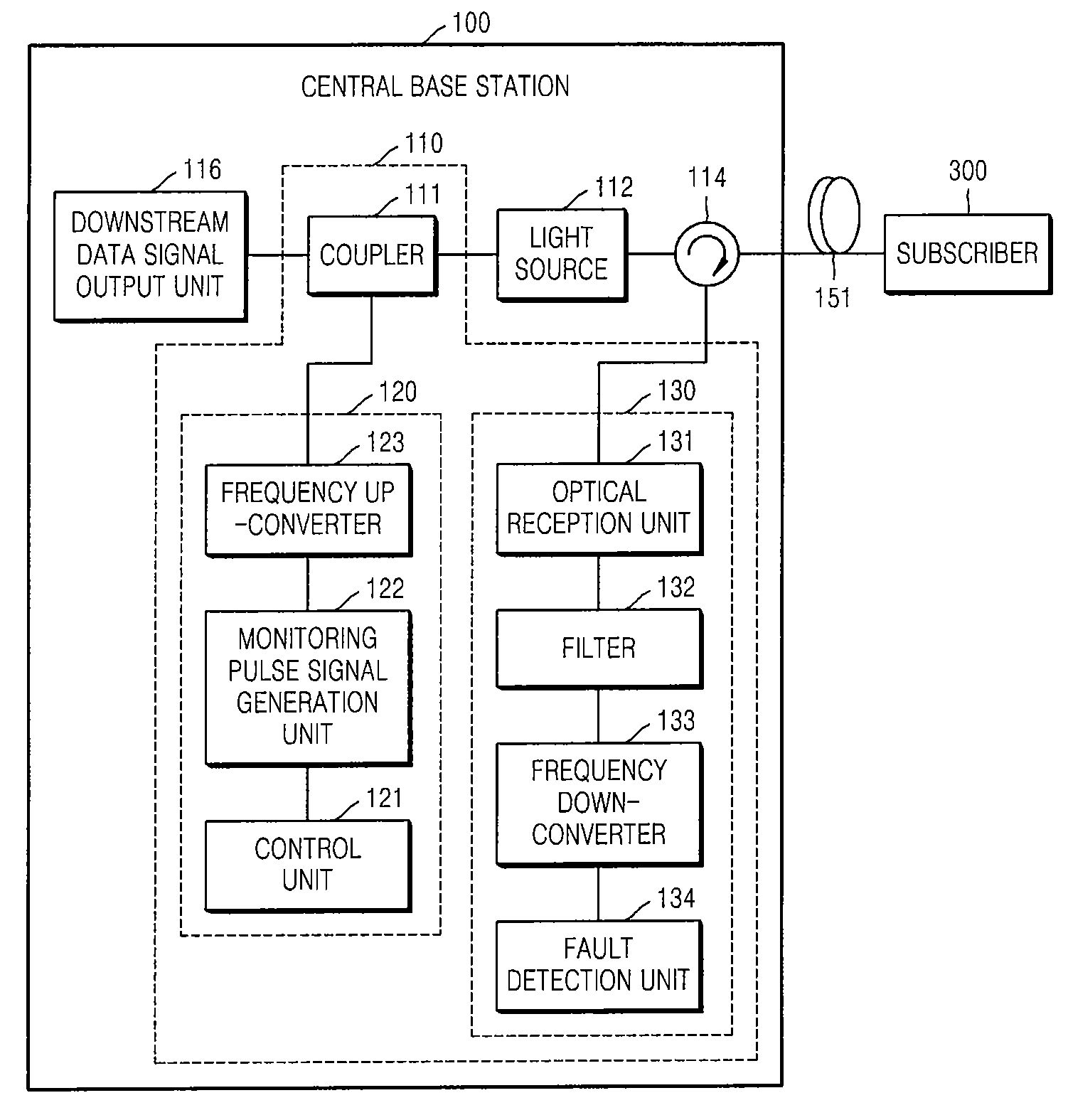
[0034]FIG. 1 is a block diagram of an optical communication network including a fault localization apparatus 110 for an optical line, according to an embodiment of the present invention. FIG. 10 is a flowchart of a fault localization method for an optical line, according to an embodiment of the present invention. Operations of the optical communication network illustrated in FIG. 1 will now be described in conjunction with the flowchart of FIG. 10.

[0035]Referring to FIG. 1, the optical communication network includes a central base station 100 and a subscr...


PUM


Abstract

Provided are a fault localization apparatus based on an optical communication network and a method thereof. In the fault localization apparatus according to the present invention, a downstream light source is used as a monitoring optical signal instead of using an additional monitoring light source and a subcarrier multiplexing (SCM) monitoring pulse signal of a certain frequency band having no interference with a frequency band of a downstream data signal is used and thus a fault position may be detected at low cost.

Description

CROSS-REFERENCE TO RELATED PATENT APPLICATION[0001]This application claims the benefit of Korean Patent Application No. 10-2006-0122572, filed on Dec. 5, 2006 and Korean Patent Application No. 10-2007-0050243, filed on May 23, 2007, in the Korean Intellectual Property Office, the disclosures of which are incorporated herein in their entirety by reference.BACKGROUND OF THE INVENTION[0002]1. Field of the Invention[0003]The present invention relates to a fault localization apparatus based on an optical communication network and a method thereof, and more particularly, to a fault localization apparatus for an optical line using a downstream light source as a monitoring light source instead of using an additional monitoring light source, and a method thereof.[0004]The present invention was supported by the Information Technology (IT) Research & Development (R&D) program of the Ministry of Information and Communication (MIC) [Project management number: 2005-S-401-02, Project title: Optica...

Claims


Application Information

Patent Timeline
Patent Type & Authority Applications(United States)
IPC IPC(8): H04B10/08H04B17/00H04J14/02
CPCH04B10/0771H04J14/0226H04J14/0227H04B2210/074H04J14/0298H04J14/0238H04J14/0246H04J14/0282H04B10/00H04B10/07H04B10/25
Inventor JANG, SEUNG-HYUNLEE, CHUL-SOOJUNG, EUI SUKKIM, BYOUNG WHI
Owner ELECTRONICS & TELECOMM RES INST
Why Eureka
Try Eureka