
Brace for use with an external fixation device

a technology for fixing devices and braces, applied in the field of therapeutic braces, can solve the problems of skin irritation around the site where the wire is inserted through the leg, the wire may need to be replaced, and the wire may not be safe to us

Inactive Publication Date: 2008-06-05
VITO GEORGE R
View PDF6 Cites 12 Cited by
  • Summary
  • Abstract
  • Description
  • Claims
  • Application Information

AI Technical Summary

Benefits of technology

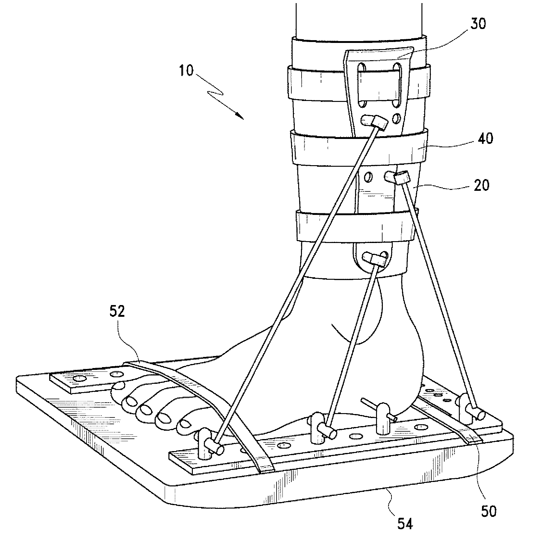
[0012]In yet another aspect of the invention, an external fixation device is provided for use with a foot reconstruction technique, the technique comprising inserting pins through a patient's foot and securing the pins to a foot frame at least partially surrounding the patient's foot. The fixation device includes a sleeve, a pair of braces, and at least one removable strap The sleeve is open on opposite ends and is selectively attachable over a portion of the patient's leg. The braces are disposed on the sleeve on opposite sides of the patient's leg, generally along the patient's leg. The at least one removable strap is used for securing at least one of the sleeve and the braces relative to the patient's leg. A plurality of rods are secured proximate opposite ends to the foot frame and one of the braces to substantially inhibit movement of the foot frame relative to the braces, and thus immobilize the patient's foot relative to the patient's leg.

Problems solved by technology

Of course, the insertion of wires through one's skin and bones is not without some medical risks.
For example, skin irritation around the site at which the wire is inserted through the leg is not uncommon.
Furthermore, if a wire breaks, the wire may need to be replaced.
More serious risks, such as neurological damage resulting from improper drilling for insertion of the wires may result in irreversible problems.
Moreover, the Ilizarov procedure also creates several problems with respect to post operative care and recovery.
However, the boot of the '633 patent also has several drawbacks.
For example, the boot is complex and costly to manufacture.
Furthermore, the boot is not adaptable to conventional foot plates, and is not easily removable for purposes of inspecting / cleaning the patient's lower leg.

Method used


Image

  • Brace for use with an external fixation device
  • Brace for use with an external fixation device
  • Brace for use with an external fixation device

Examples


Embodiment Construction

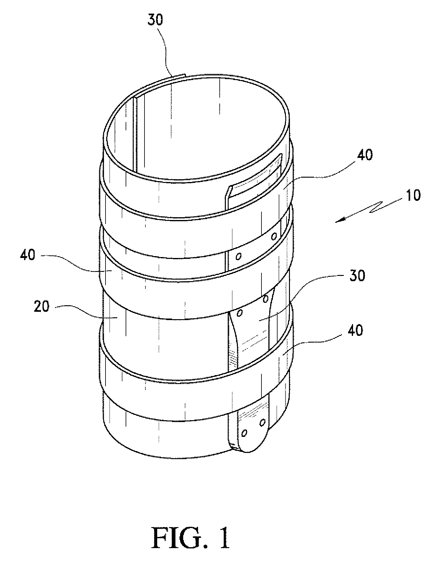
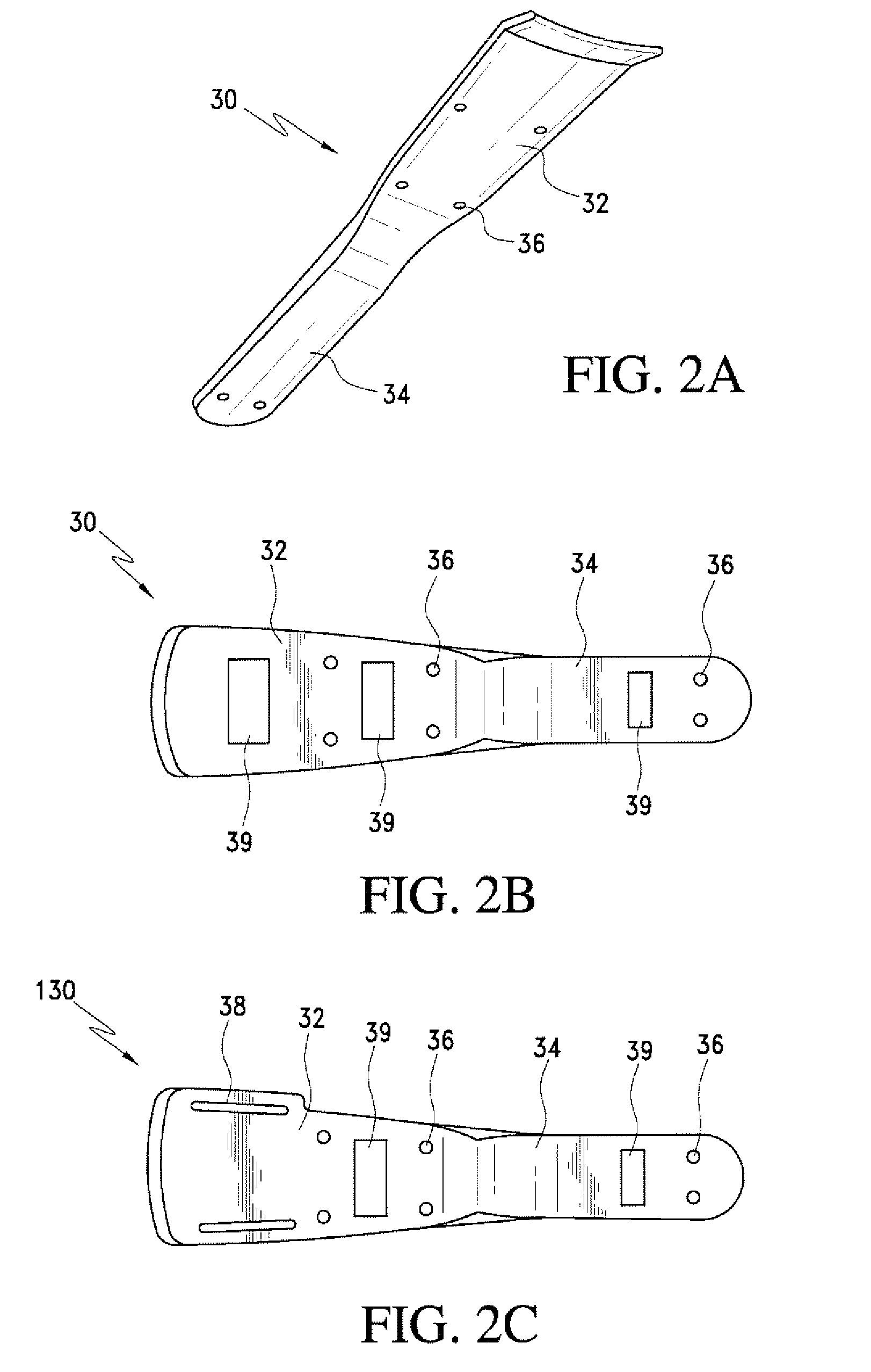
[0017]Preferred embodiments of the present invention will be described with reference to the Figures. FIGS. 1 through 3 show a first preferred embodiment of the invention. As illustrated in FIG. 1, an immobilization apparatus 10 according to the present invention includes a sleeve 20, a pair of braces 30, and a plurality of straps 40.

[0018]The sleeve 20 preferably is selectively attachable to a patient's leg. The sleeve 20 may be an elastic sheath to be slipped over the foot, but preferably is a unitary piece shaped substantially rectangularly. This rectangular piece is rolled or wrapped around the leg and subsequently secured firmly about the leg. Preferably, the sleeve utilizes hook and loop fasteners as a means for fastening the sleeve about the legs. More specifically, an outer portion of the sleeve may comprise the loop portion of the hook and loop fastener while a strip of hooks are formed on a facing part of the sleeve, in this manner, the sheath is adjustable to fit numerous...


PUM


Abstract

An external fixation device is provided for substantially immobilizing a patient's foot relative to the patient's leg, after a conventional procedure in which wires are disposed through the foot and opposite ends of the pins are secured to a foot frame arranged proximate the patient's foot. The fixation device includes a pair of braces, a cushion, and a fastener. The braces are arranged on opposite sides of the patient's leg, and each has a plurality of attachment points for selectively receiving a first end of a stabilizing rod. The cushion is disposed between each of the braces and the patient's leg. The fastener secures the braces and the cushion relative to the patient's leg. The stabilizing rod is adjustably secured proximate a second end to the foot frame.

Description

BACKGROUND OF THE INVENTION[0001]1. Field of the Invention[0002]The present invention relates generally to therapeutic devices for use with known bone fixation procedures. More specifically, the invention relates to a therapeutic brace for immobilizing a foot and ankle with respect to a leg.[0003]2. Description of Related Art[0004]Procedures are well known for correcting bone fractures and deformities, and in particular fractures and deformities to the foot and ankle. At least one of those procedures was introduced by Dr. Ilizarov. As applied to a foot deformity, the Ilizarov procedure involves inserting wires percutaneously through bones or bone segments of the foot. Opposite ends of the wire are then secured to a frame disposed about all or a portion of the foot.[0005]As is also generally understood, once the bones in the foot an / or ankle are appropriately aligned using the wires, it is desirable to prohibit movement of the foot with respect to the leg. To this end, the Ilizarov p...

Claims


Application Information

Patent Timeline
Patent Type & Authority Applications(United States)
IPC IPC(8): A61F5/01
CPCA61F5/0585A61F5/0111
Inventor VITO, GEORGE R.
Owner VITO GEORGE R
Learn More