
Sanitary cove molding system

Inactive Publication Date: 2008-06-12
SCHICK ERIC
View PDF19 Cites 22 Cited by
  • Summary
  • Abstract
  • Description
  • Claims
  • Application Information

AI Technical Summary

Benefits of technology

[0008]The present invention achieves these and other objectives through its design and structure. It can provide a sanitary transition between a wall and a floor by smoothing out and raising the surface away from a sharp corner or crevice, to allow for easier cleaning. The invention also may decrease the number of seams and the amount of exposed grout by moving the grout joint and edges of the molding piece farther away from the inside corner. This also improves cleanliness. The structure of the invention can provide for a smoother installation and more uniform molding scheme by improving the stability of the design with the use of a right-angle, rather than a triangle or point, to allow the molding piece to lie flush in the corner. All of the features of the invention may promote easier installation, better sanitation, and a pleasing appearance to the molding scheme.

Problems solved by technology

Dirt and germs often become trapped in the corners between the walls and the floor, and within the grout between individual tiles.
Molding is often used to raise and smooth out those crevices and corners, and may decrease the amount of exposed grout.
First, installation of this molding may present challenges.
The current corner molding lacks stability and it is difficult to install in isolation without support from the neighboring baseboard molding pieces.
Furthermore, if corner moldings are installed last to improve the stability, variations in the lengths of the baseboard moldings may create gaps which may result in an increase of exposed grout.
Both these situations may greatly decrease uniformity throughout the scheme and negatively impact the aesthetic value of the molding.
Secondly, an increase in the amount of grout exposed may make sanitation more difficult and the presentation of the molding more abrasive, as does an increase in the number of seams existing between the various molding pieces.

Method used


Image

  • Sanitary cove molding system
  • Sanitary cove molding system
  • Sanitary cove molding system

Examples


Embodiment Construction

[0022]The entire contents of Provisional Patent Application Ser. No. 60 / 864,862, entitled: “SANITARY COVE MOLDING” filed on Nov. 8, 2006, including appendices, are incorporated herein by reference for all purposes.

[0023]In the following discussion, numerous specific details are set forth to provide a thorough understanding of the present invention. However, those skilled in the art will appreciate that the present invention may be practiced without such specific details. In other instances, well-known elements have been illustrated in schematic or block diagram form in order not to obscure the present invention in unnecessary detail. Additionally, for the most part, details concerning installation procedures, materials, and the like, have been omitted to the extent that such details are not considered necessary to obtain a complete understanding of the present invention, and are considered to be within the understanding of persons of ordinary skill in the relevant art.
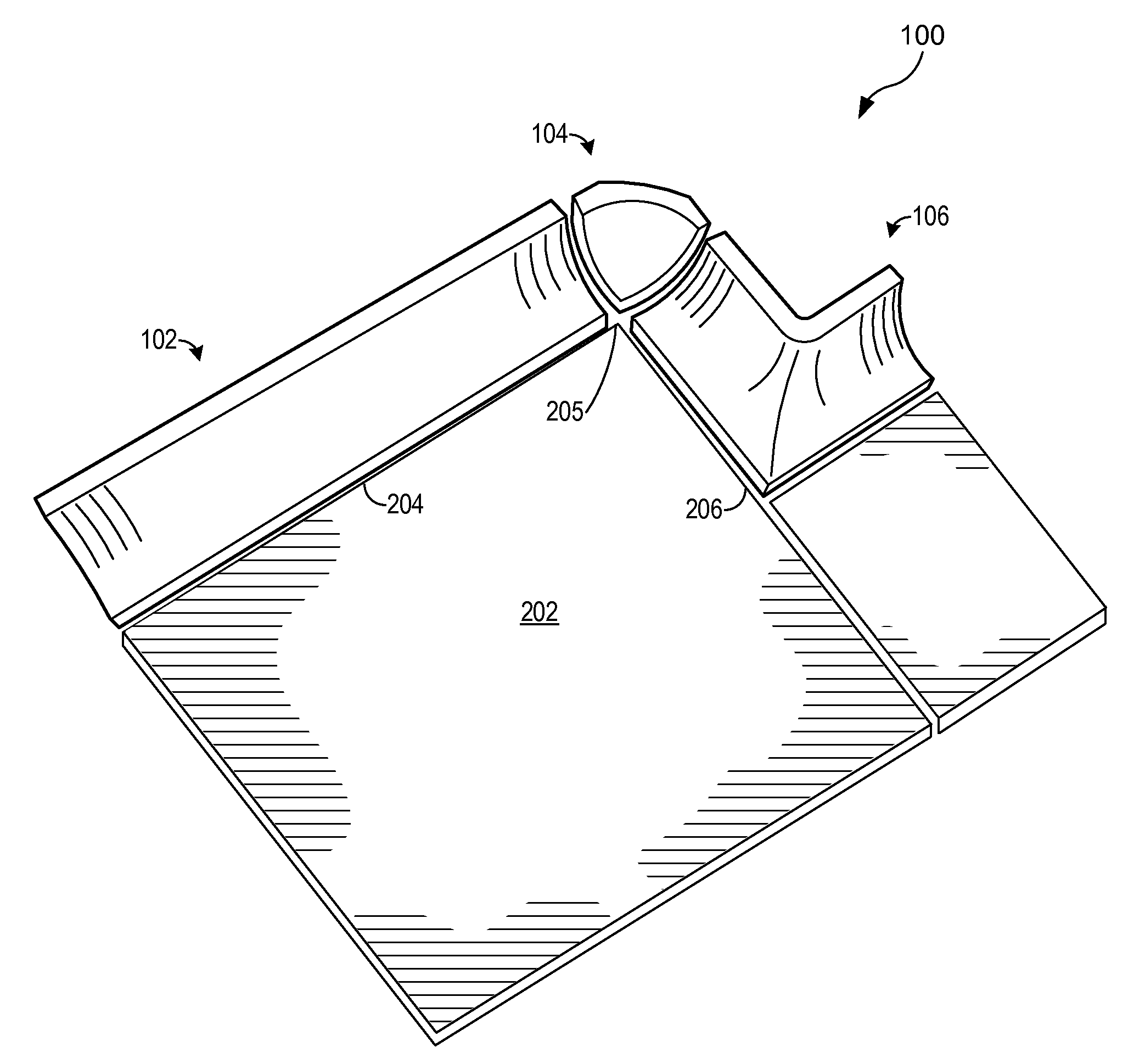
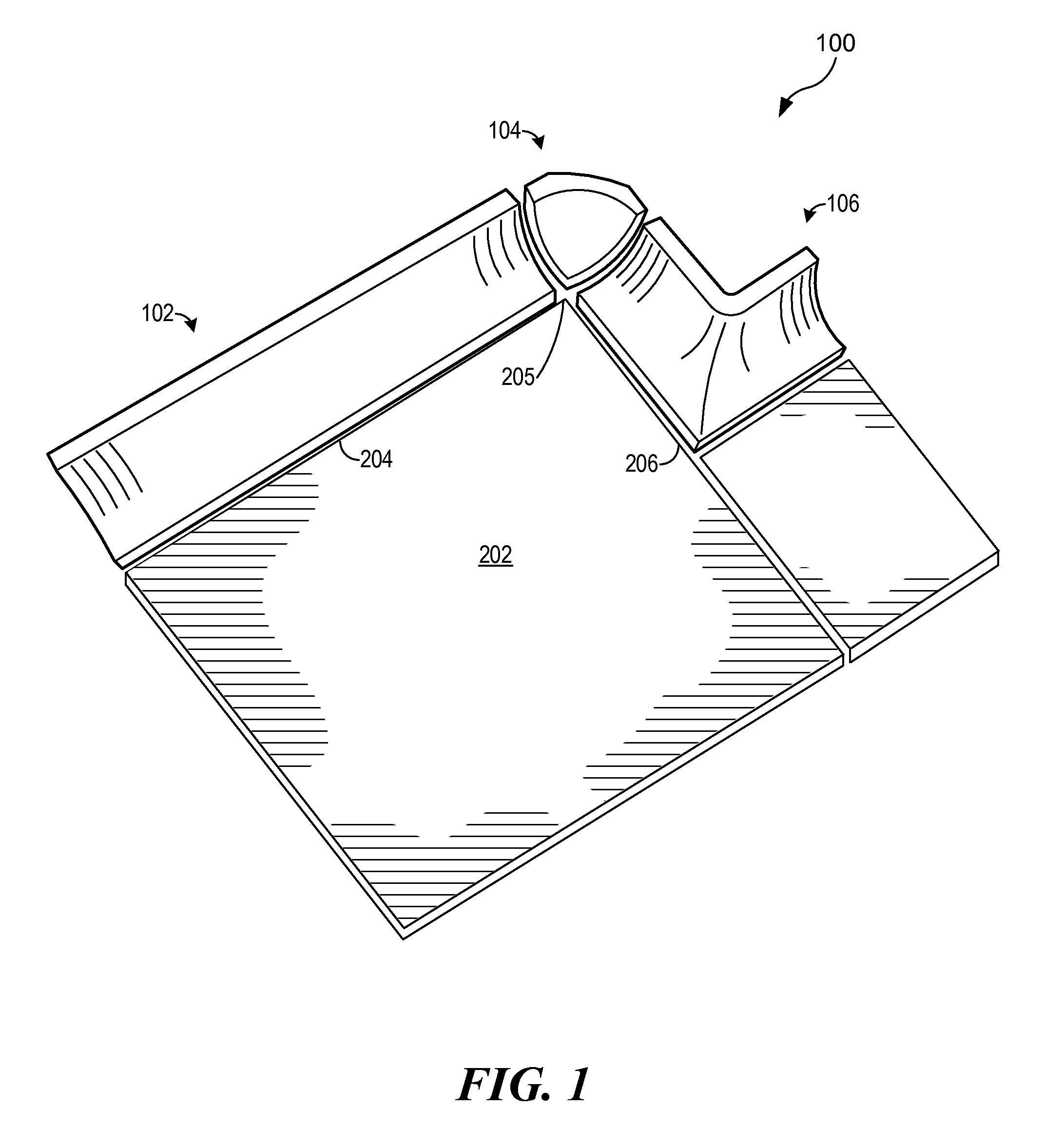
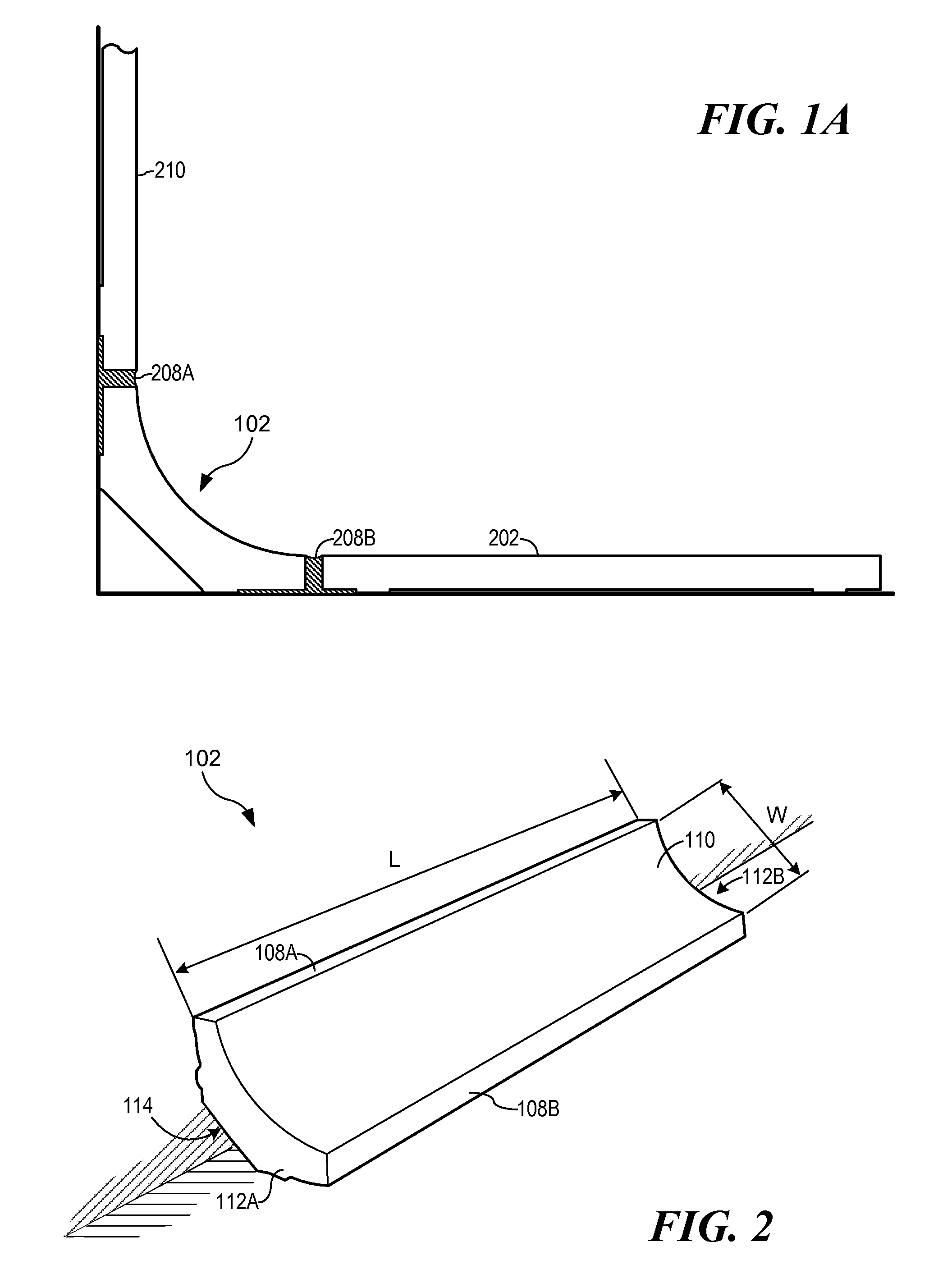
[0024]Turning ...


PUM


Abstract

The present invention extends an interior corner piece to create flange portions of a ceramic or porcelain molding. The structure of the invention can provide a sanitary transition between a wall and a floor by smoothing out and raising the surface away from a sharp corner or crevice. The invention also moves edges of the corner piece farther away from the inside corner. This can improve sanitation and allow for easier cleaning. This structure can promote a smoother installation and more uniform molding scheme by possibility improving the stability of the design to allow the molding piece to lie flush in the corner. The features of the invention may promote easier installation, better sanitation, and a pleasing appearance to the molding scheme.

Description

CROSS-REFERENCE TO RELATED APPLICATIONS[0001]This application relates to, and claims the benefit of the filing date of, co-pending U.S. provisional patent application Ser. No. 60 / 864,862 entitled SANITARY COVE MOLDING, filed Nov. 8, 2006, the entire contents of which are incorporated herein by reference for all purposes.BACKGROUND OF THE INVENTION[0002]1. Field of the Invention[0003]The present invention relates to floor and wall coverings and, more particularly, to sanitary ceramic or porcelain cove moldings to be used in transition from floor to wall coverings.[0004]2. Description of Related Art[0005]Ceramic or porcelain moldings are used for various purposes. Molding does not only increase the aesthetic value of the environment in which it is used, but impervious molding may also improve sanitation and cleanliness. Dirt and germs often become trapped in the corners between the walls and the floor, and within the grout between individual tiles. Molding is often used to raise and s...

Claims


Application Information

Patent Timeline
IPC IPC(8): E04F19/02
CPCE04F19/022E04F19/045E04F19/0477E04F2019/0418E04F19/049E04F19/0495E04F19/0486
Inventor SCHICK, ERIC
Owner SCHICK ERIC
Features
  • Generate Ideas
  • Intellectual Property
  • Life Sciences
  • Materials
  • Tech Scout
  • Unparalleled Data Quality
  • Higher Quality Content
  • 60% Fewer Hallucinations
Learn More